
MOLUN

ESP32-S3 Reverse TFT Feather开箱
产品概述
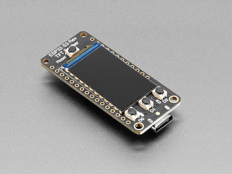
Adafruit Feather ESP32-S3 Reverse TFT 是一款基于 ESP32-S3 芯片的高性能开发板,特色在于将 1.14 英寸 TFT 显示屏放置在板子背面,特别适合面板安装项目。这款开发板继承了 Feather 系列的优良传统,体积小巧但功能强大,支持 WiFi 和蓝牙低功耗通信。
主要特色
- 反向显示屏设计:1.14 英寸 TFT 显示屏位于板子背面,便于面板安装
- 高性能处理器:ESP32-S3 双核 240MHz 处理器
- 丰富存储:4MB Flash + 2MB PSRAM
- 低功耗优化:深度睡眠模式仅 40-50uA 电流消耗
- 完整生态:兼容 Feather Wings 扩展板
技术规格
核心处理器
| 参数 | 规格 |
|---|---|
| 处理器 | ESP32-S3 双核 240MHz Tensilica LX7 |
| 架构 | Xtensa 32 位 |
| SRAM | 512KB |
| Flash | 4MB QSPI Flash |
| PSRAM | 2MB QSPI PSRAM |
| 无线通信 | 2.4GHz WiFi 802.11 b/g/n + Bluetooth 5.0 BLE |
显示屏参数
| 参数 | 规格 |
|---|---|
| 尺寸 | 1.14 英寸 |
| 分辨率 | 240x135 像素 |
| 类型 | IPS 彩色 TFT |
| 驱动芯片 | ST7789 |
| 可视角度 | 178° 全视角 |
| 背光控制 | PWM 可调 |
电源规格
| 参数 | 规格 |
|---|---|
| 供电方式 | USB Type-C 或 LiPoly 电池 |
| 工作电压 | 3.3V |
| 充电电流 | 100mA (LiPoly 电池) |
| 深度睡眠电流 | 40-50uA |
| 工作温度 | -40°C 至 85°C |
硬件特点
外设接口
- USB 接口:USB Type-C 原生 USB,支持模拟键盘、鼠标、MIDI 设备等
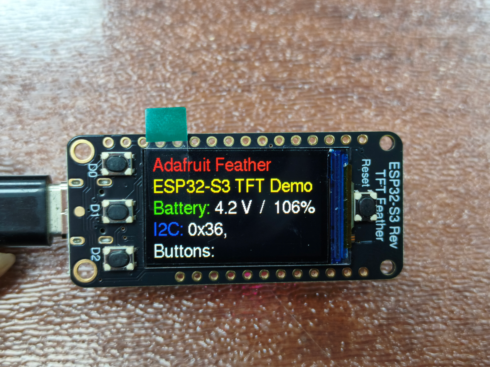
- 用户按钮:3 个用户按键(D0、D1、D2),D0 同时作为 BOOT0 引脚
- 状态指示:电源 LED、充电 LED、用户 LED + NeoPixel RGB 灯
- 扩展接口:STEMMA QT I2C 接口,支持热插拔
- 电池管理:MAX17048 电池监视器,支持电压和电量百分比监测
低功耗设计
- 双重 LDO 稳压器:主稳压器 + 外设专用稳压器
- 外设电源控制:TFT 显示屏和 STEMMA QT 接口可单独断电
- NeoPixel 电源控制:可单独关闭以节省功耗
- 深度睡眠优化:所有外设可关闭,仅核心保持最低功耗
开发工具
- Arduino IDE
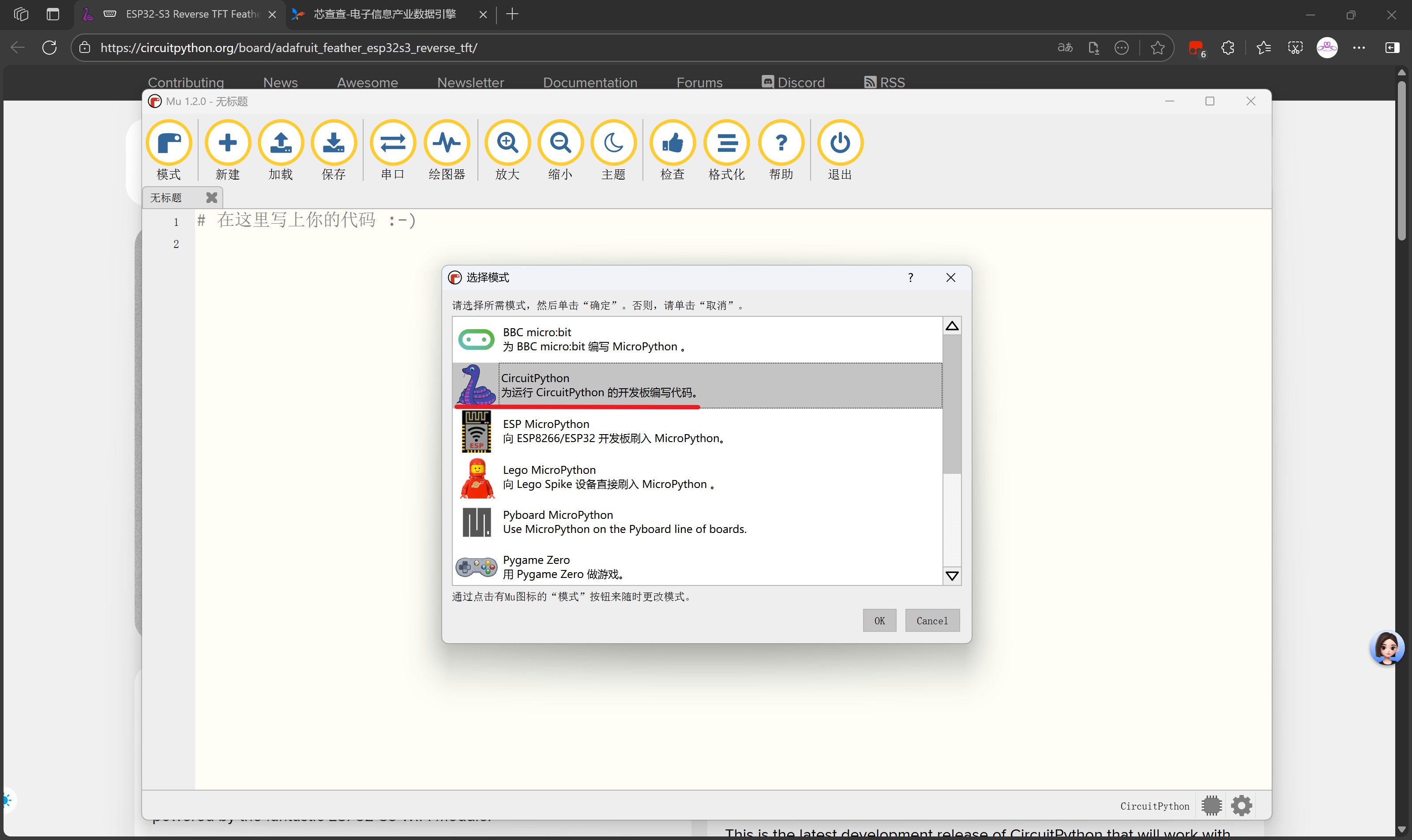
- CircuitPython
- PlatformIO
- ESP-IDF
开发环境搭建
Arduino IDE 设置
1. 安装开发板支持包
- 打开 Arduino IDE,进入「文件」→「首选项」
- 在「附加开发板管理器网址」中添加:
https://raw.githubusercontent.com/espressif/arduino-esp32/gh-pages/package_esp32_index.json- 进入「工具」→「开发板」→「开发板管理器」
- 搜索「ESP32」,安装「esp32 by Espressif Systems」
- 选择开发板:「工具」→「开发板」→「ESP32 Arduino」→「Adafruit Feather ESP32-S3 Reverse TFT」
2. 安装必要库
arduino
// 核心库
#include <Arduino.h>
#include <WiFi.h>
#include <BluetoothSerial.h>

// TFT显示库
#include <TFT_eSPI.h>
#include <Adafruit_GFX.h>
#include <Adafruit_ST7789.h>

// 其他常用库
#include <Wire.h>
#include <SPIFFS.h>
#include <Adafruit_NeoPixel.h>
CircuitPython 设置
1. 安装 CircuitPython 固件
- 下载适用于 Adafruit Feather ESP32-S3 Reverse TFT 的 CircuitPython 固件
- 将开发板进入 BOOT 模式(按住 BOOT 按钮,按一下 RESET 按钮)
- 将固件文件复制到显示为 U 盘的开发板中
2. 必需库文件
python
# 核心模块
import board
import digitalio
import time
import busio
import neopixel

# 显示模块
import displayio
import adafruit_st7789
from adafruit_display_text import label
from adafruit_bitmap_font import bitmap_font

# 通信模块
import wifi
import socketpool
import adafruit_requests

# 传感器模块
import adafruit_max17048
PlatformIO 设置
platformio.ini 配置文件
ini
[env:adafruit_feather_esp32s3_reverse_tft]
platform = espressif32
board = adafruit_feather_esp32s3_reverse_tft
framework = arduino

; 编译选项
board_build.mcu = esp32s3
board_build.f_cpu = 240000000L

; 上传设置
upload_protocol = esptool
upload_speed = 921600

; 调试设置
debug_tool = esp-prog

; 库依赖
lib_deps =
    bodmer/TFT_eSPI@^2.5.43
    adafruit/Adafruit GFX Library@^1.11.9
    adafruit/Adafruit NeoPixel@^1.12.0
编程示例
基础示例:点亮内置 LED
Arduino 代码
arduino
#include <Arduino.h>

const int ledPin = LED_BUILTIN;

void setup() {
  pinMode(ledPin, OUTPUT);
  Serial.begin(115200);
  Serial.println("LED Blink Example");
}

void loop() {
  digitalWrite(ledPin, HIGH);
  Serial.println("LED ON");
  delay(1000);

  digitalWrite(ledPin, LOW);
  Serial.println("LED OFF");
  delay(1000);
}
CircuitPython 代码
python
import board
import digitalio
import time

led = digitalio.DigitalInOut(board.LED)
led.direction = digitalio.Direction.OUTPUT

print("LED Blink Example")

while True:
    led.value = True
    print("LED ON")
    time.sleep(1.0)

    led.value = False
    print("LED OFF")
    time.sleep(1.0)
TFT 显示屏示例
Arduino + TFT_eSPI
arduino
#include <TFT_eSPI.h>

TFT_eSPI tft = TFT_eSPI();

void setup() {
  Serial.begin(115200);

  // 初始化TFT显示屏
  tft.init();
  tft.setRotation(1);  // 设置屏幕旋转
  tft.fillScreen(TFT_BLACK);

  // 显示标题
  tft.setTextColor(TFT_WHITE, TFT_BLACK);
  tft.setTextSize(2);
  tft.setCursor(20, 10);
  tft.println("ESP32-S3 Reverse TFT");

  // 显示系统信息
  tft.setTextSize(1);
  tft.setCursor(10, 40);
  tft.println("Processor: ESP32-S3");
  tft.println("Frequency: 240MHz");
  tft.println("Flash: 4MB");
  tft.println("PSRAM: 2MB");

  // 绘制图形
  tft.drawRect(10, 100, 80, 40, TFT_RED);
  tft.fillRect(100, 100, 80, 40, TFT_GREEN);
  tft.drawCircle(60, 170, 30, TFT_BLUE);
}

void loop() {
  // 更新时间显示
  tft.setTextColor(TFT_YELLOW, TFT_BLACK);
  tft.setCursor(10, 80);
  tft.print("Time: ");
  tft.print(millis() / 1000);
  tft.println("s");

  delay(1000);
}
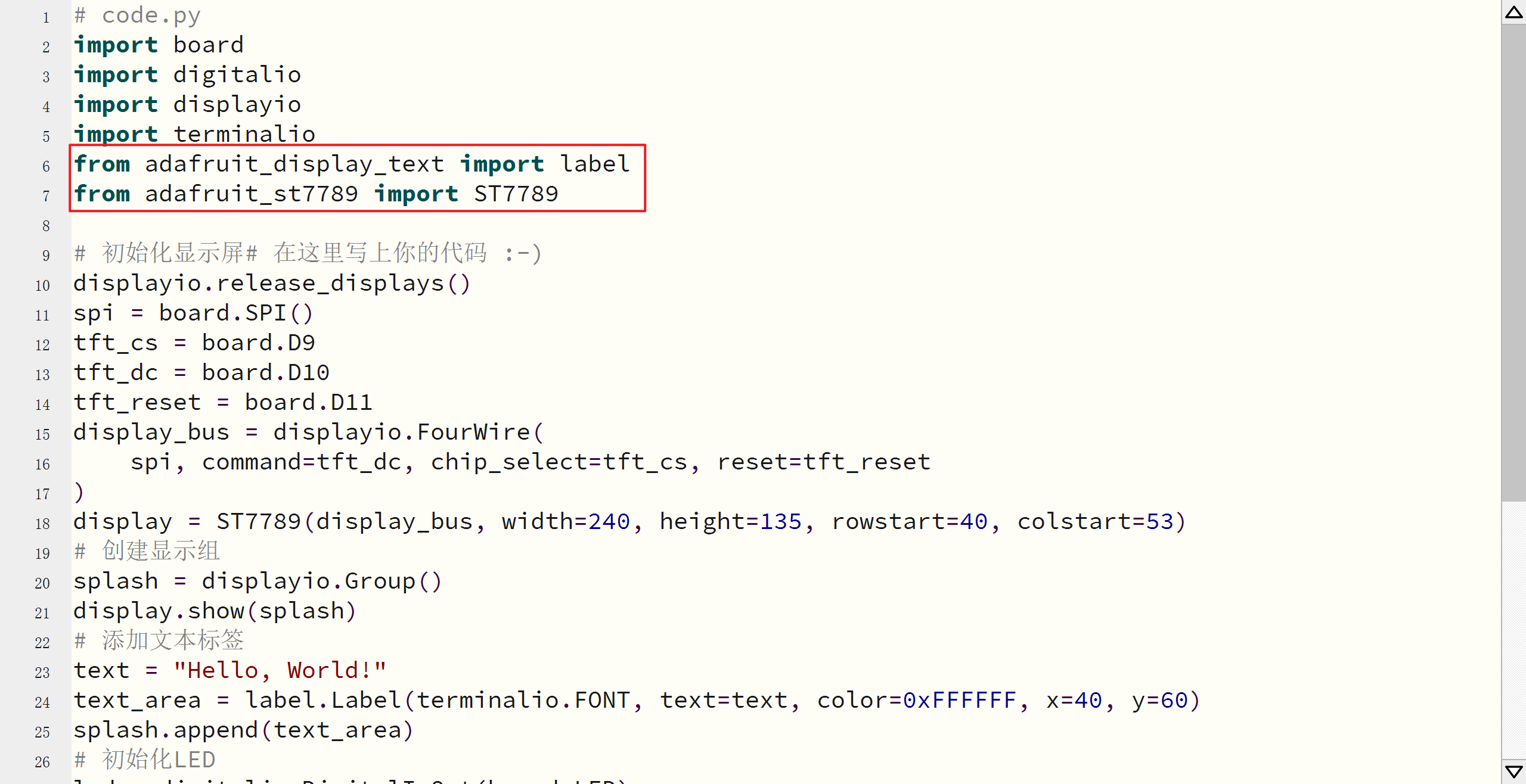
CircuitPython 显示示例
python
import board
import displayio
import adafruit_st7789
from adafruit_display_text import label
from adafruit_bitmap_font import bitmap_font
import time

# 释放显示资源
displayio.release_displays()

# 初始化SPI
spi = board.SPI()
tft_cs = board.TFT_CS
tft_dc = board.TFT_DC
tft_reset = board.TFT_RST

# 初始化显示屏
display_bus = displayio.FourWire(
    spi, command=tft_dc, chip_select=tft_cs, reset=tft_reset
)
display = adafruit_st7789.ST7789(
    display_bus, width=240, height=135, rowstart=40, colstart=53
)

# 创建显示组
splash = displayio.Group()
display.show(splash)

# 加载字体
font = bitmap_font.load_font("/fonts/Helvetica-Bold-16.bdf")

# 创建文本标签
title_text = "ESP32-S3 Reverse TFT"
title_label = label.Label(font, text=title_text, color=0xFFFFFF)
title_label.x = 20
title_label.y = 10
splash.append(title_label)

# 系统信息
info_text = [
    "Processor: ESP32-S3",
    "Frequency: 240MHz",
    "Flash: 4MB",
    "PSRAM: 2MB"
]

y_pos = 40
for text in info_text:
    info_label = label.Label(font, text=text, color=0xFFFFFF)
    info_label.x = 10
    info_label.y = y_pos
    splash.append(info_label)
    y_pos += 20

# 时间显示
time_label = label.Label(font, text="Time: 0s", color=0xFFFF00)
time_label.x = 10
time_label.y = 120
splash.append(time_label)

# 主循环
start_time = time.monotonic()
while True:
    elapsed = time.monotonic() - start_time
    time_label.text = f"Time: {elapsed:.1f}s"
    time.sleep(0.1)
WiFi 连接示例
arduino
#include <Arduino.h>
#include <WiFi.h>
#include <TFT_eSPI.h>

TFT_eSPI tft = TFT_eSPI();

const char* ssid = "your_wifi_ssid";
const char* password = "your_wifi_password";

void setup() {
  Serial.begin(115200);
  tft.init();
  tft.setRotation(1);
  tft.fillScreen(TFT_BLACK);

  // 显示WiFi连接状态
  tft.setTextColor(TFT_WHITE);
  tft.setTextSize(2);
  tft.setCursor(20, 10);
  tft.println("WiFi Connect");

  tft.setTextSize(1);
  tft.setCursor(10, 40);
  tft.print("SSID: ");
  tft.println(ssid);

  // 连接WiFi
  WiFi.begin(ssid, password);

  tft.setCursor(10, 60);
  tft.print("Connecting...");

  while (WiFi.status() != WL_CONNECTED) {
    delay(500);
    tft.print(".");
  }

  // 连接成功
  tft.fillScreen(TFT_BLACK);
  tft.setCursor(20, 10);
  tft.println("WiFi Connected!");

  tft.setCursor(10, 40);
  tft.print("IP Address: ");
  tft.println(WiFi.localIP());

  tft.setCursor(10, 60);
  tft.print("RSSI: ");
  tft.print(WiFi.RSSI());
  tft.println(" dBm");
}

void loop() {
  // 显示WiFi状态
  tft.setCursor(10, 80);
  tft.setTextColor(TFT_GREEN);
  tft.print("Status: Connected");

  tft.setCursor(10, 100);
  tft.print("Uptime: ");
  tft.print(millis() / 1000);
  tft.println("s");

  delay(1000);
}
低功耗模式示例
arduino
#include <Arduino.h>
#include <TFT_eSPI.h>
#include <esp_sleep.h>

TFT_eSPI tft = TFT_eSPI();

// 唤醒引脚
const int wakePin = GPIO_NUM_0;  // D0按钮

void setup() {
  Serial.begin(115200);

  // 初始化TFT
  tft.init();
  tft.setRotation(1);
  tft.fillScreen(TFT_BLACK);

  // 显示启动信息
  tft.setTextColor(TFT_WHITE);
  tft.setTextSize(2);
  tft.setCursor(20, 10);
  tft.println("Low Power Demo");

  tft.setTextSize(1);
  tft.setCursor(10, 40);
  tft.println("Press D0 to enter deep sleep");
  tft.println("Press D0 again to wake up");

  // 配置唤醒引脚
  pinMode(wakePin, INPUT_PULLUP);

  delay(5000);
}

void loop() {
  // 检查按钮是否按下
  if (digitalRead(wakePin) == LOW) {
    Serial.println("Entering deep sleep...");

    // 关闭TFT显示屏
    tft.writecommand(ST7789_SLPIN);  // 进入睡眠模式
    digitalWrite(TFT_BL, LOW);       // 关闭背光

    // 配置深度睡眠
    esp_sleep_enable_ext0_wakeup(wakePin, 0);  // 低电平唤醒
    esp_deep_sleep_start();
  }

  // 显示当前状态
  tft.setCursor(10, 80);
  tft.setTextColor(TFT_GREEN);
  tft.print("Active - Current: ~");
  tft.print(analogReadMilliVolts(34) / 1000.0);
  tft.println("V");

  delay(1000);
}
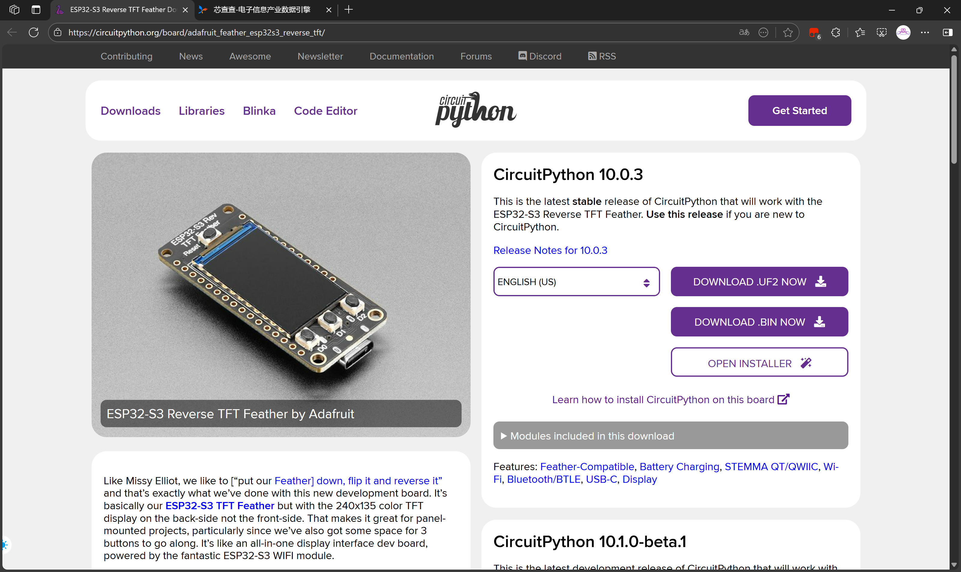
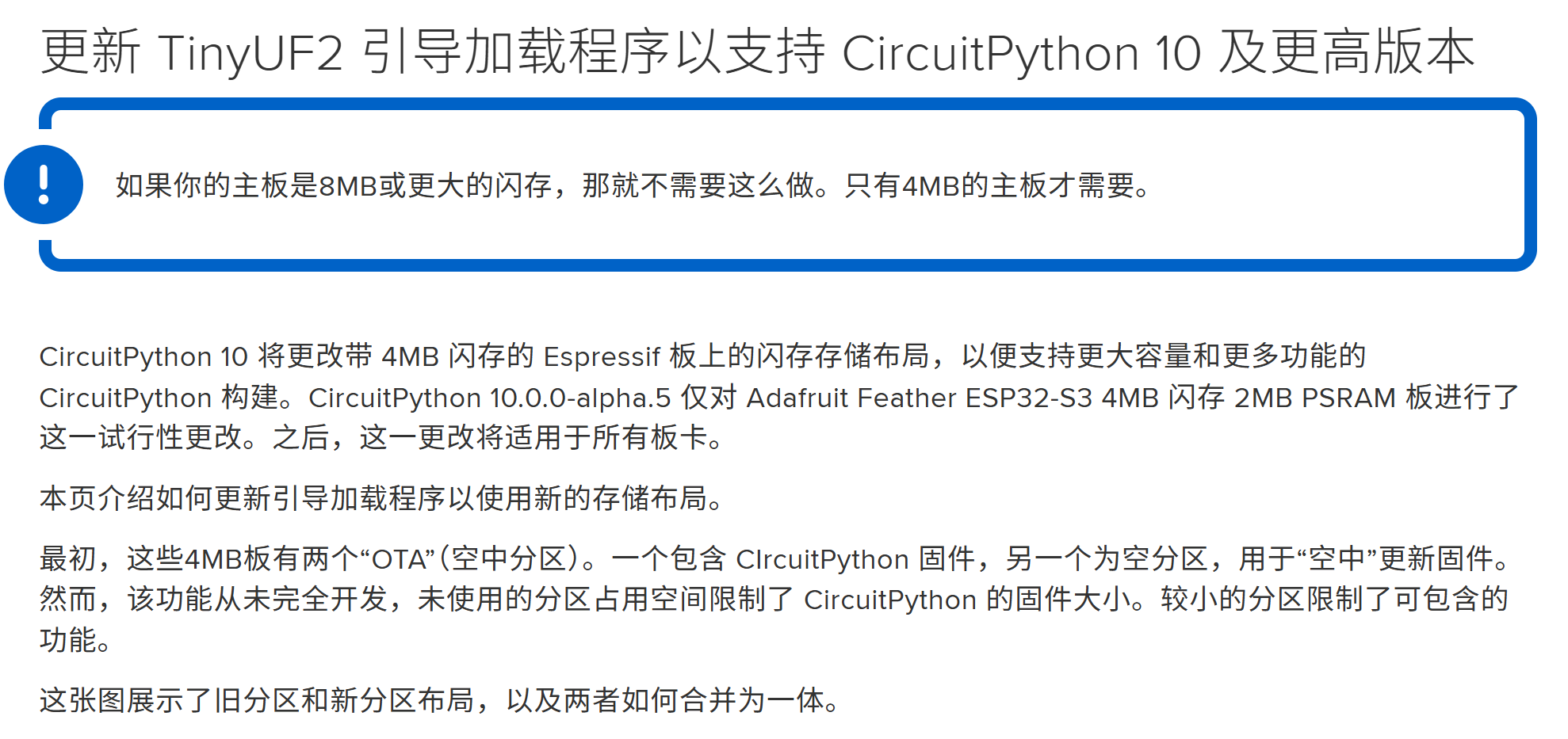
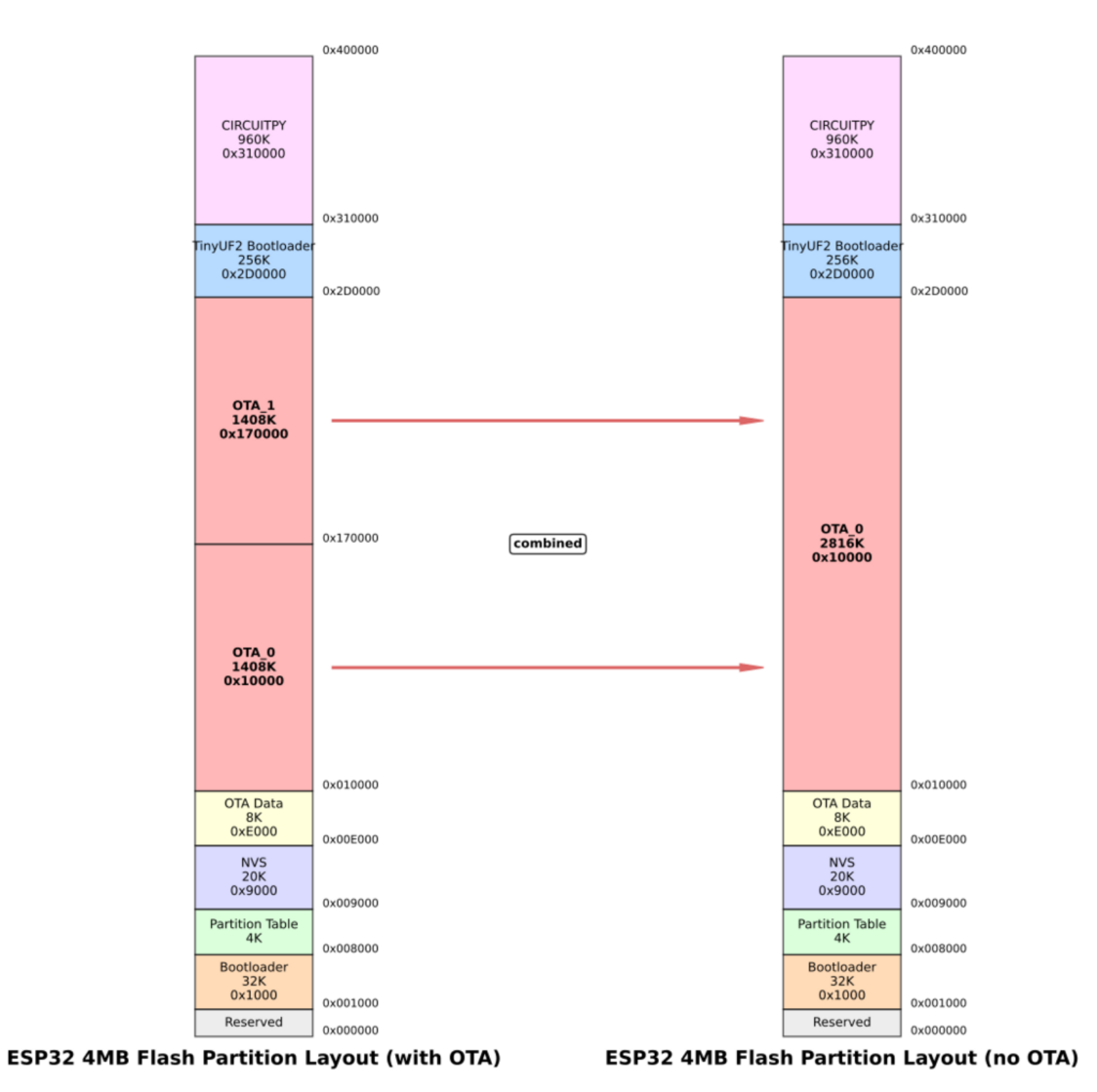

由于CircuitPython新版本修改了分区布局,因此需要CircuitPython 10之上的版本需要更新开发板的TinyUF2引导程序。
UF2引导程序下载链接:
最新版本: 0.35.0
0.33.0
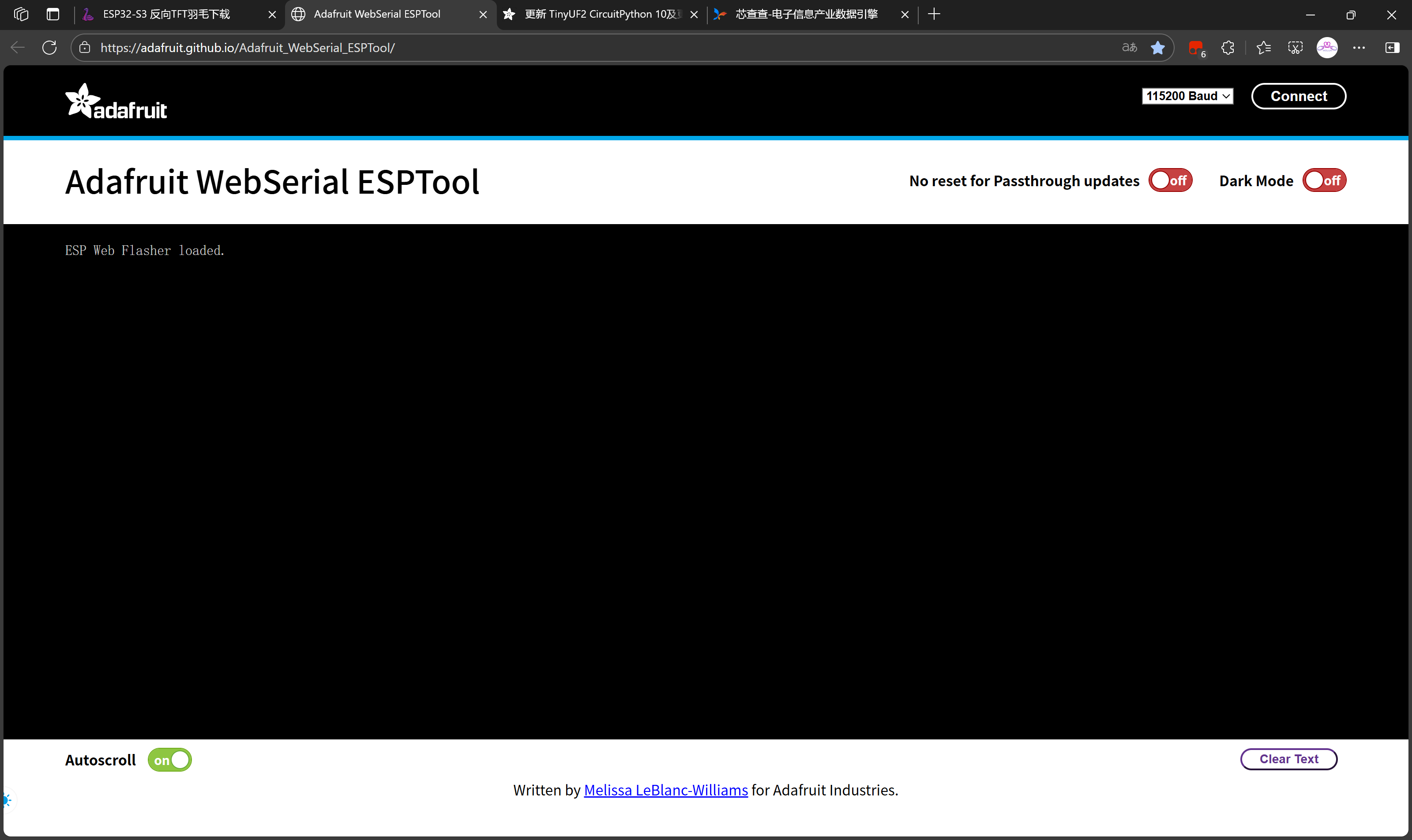
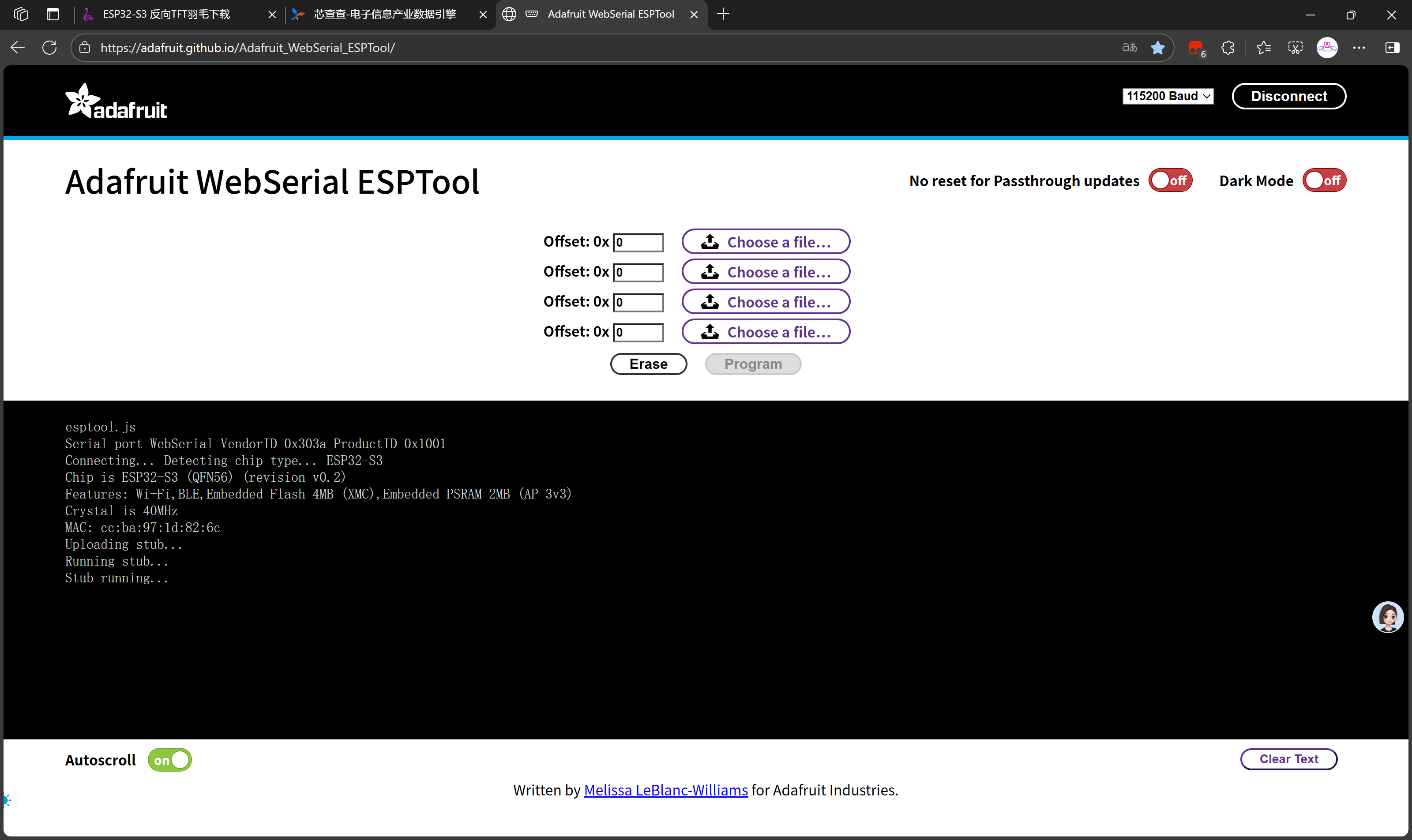
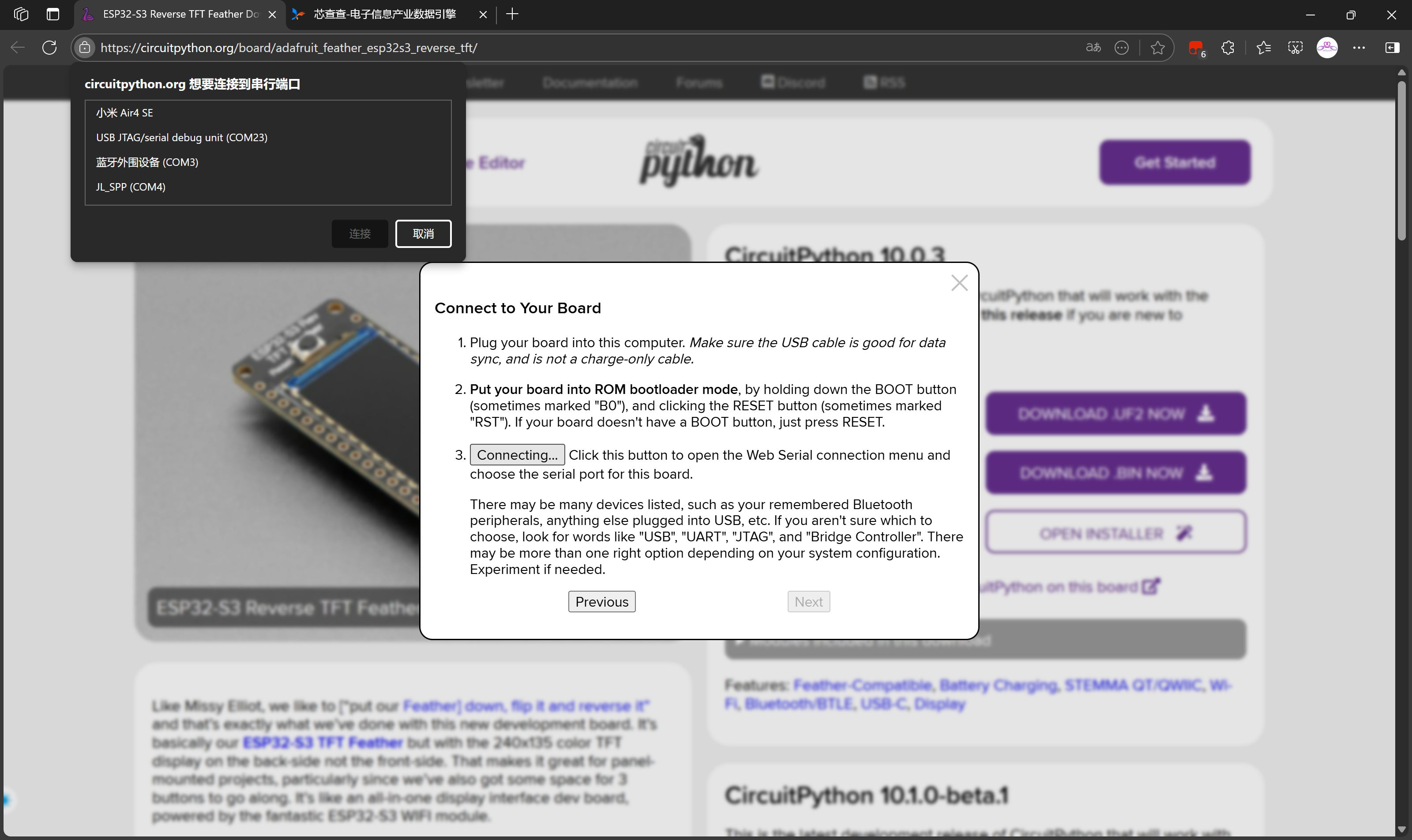
WebSerial_ESPTool烧录
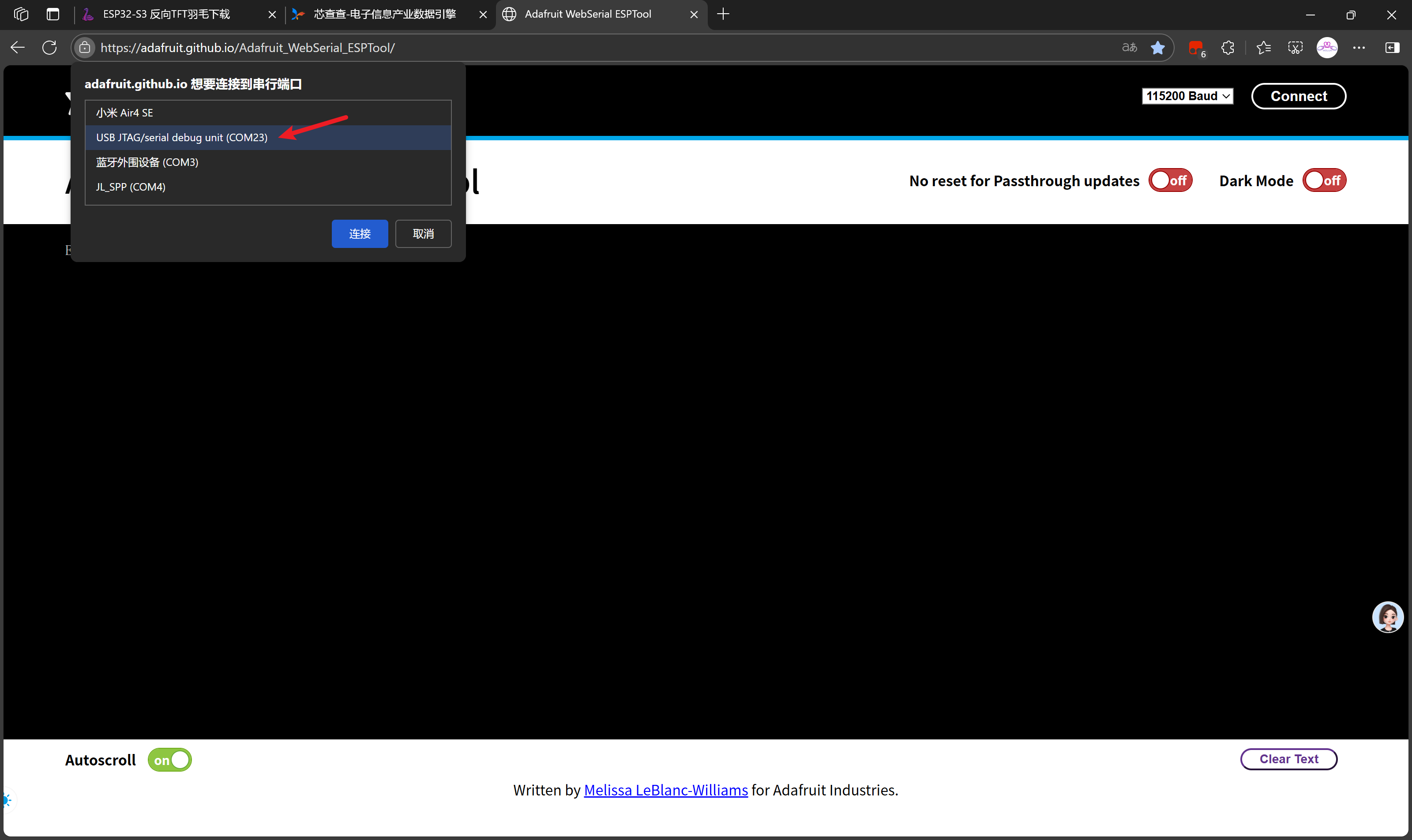
在线烧录工具:https://adafruit.github.io/Adafruit_WebSerial_ESPTool/
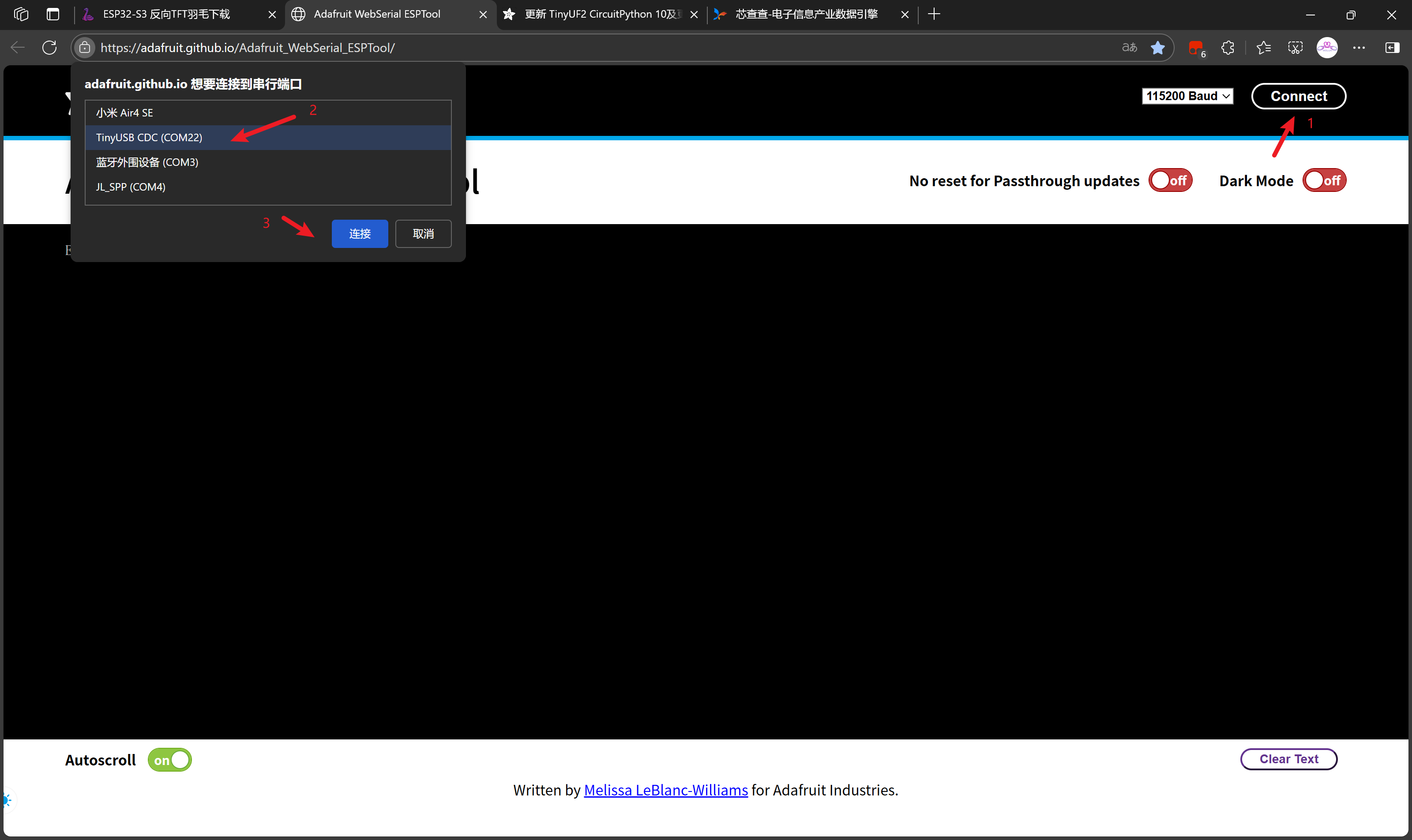
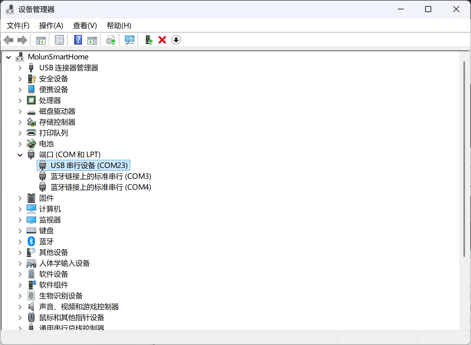
注意开发板的COM端口号,可以在设备管理器中查看,但是我不知道为何他会变化端口号!

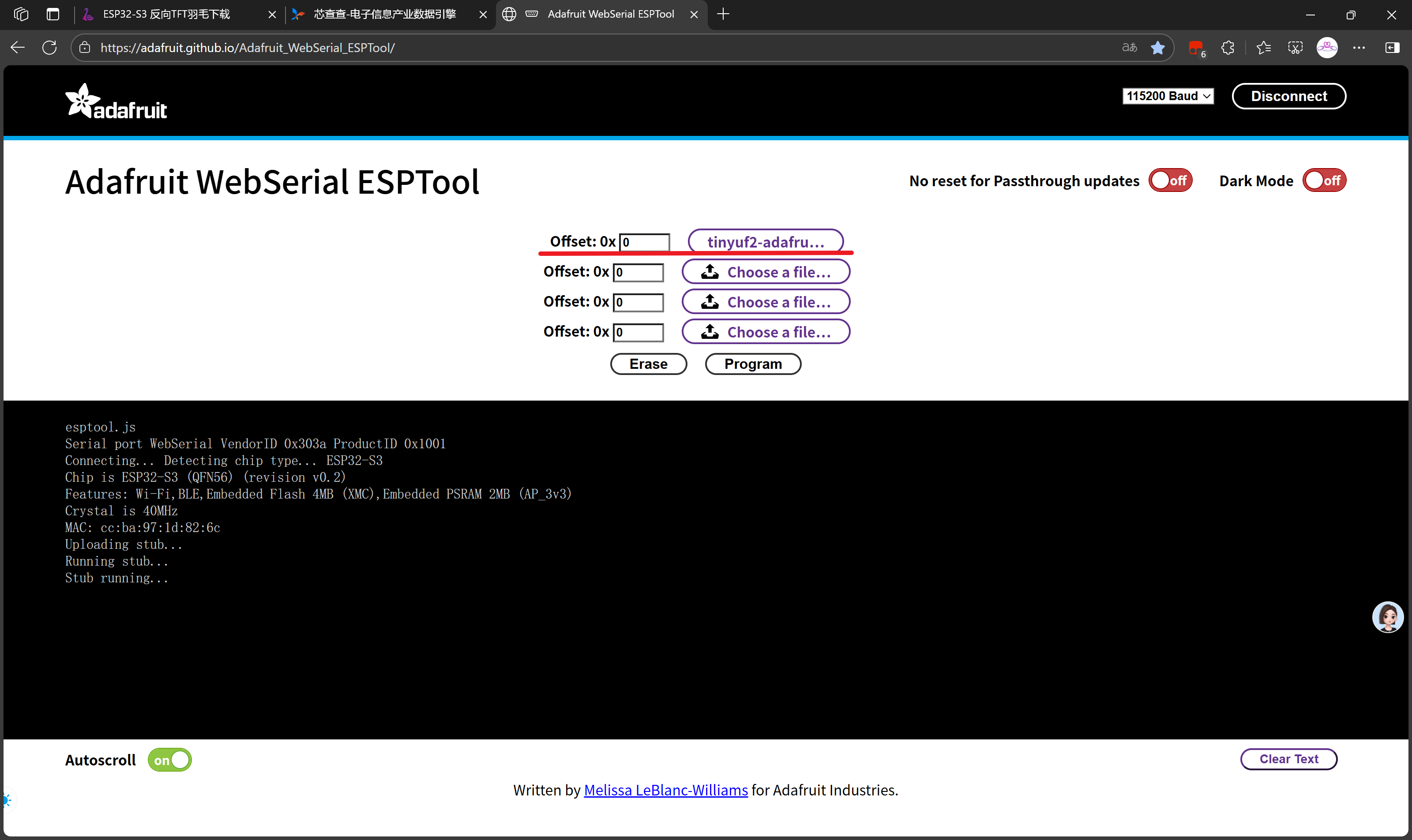
选取最新引导固件
tinyuf2-adafruit_feather_esp32s3_reverse_tft-0.35.0-combined.bin当然,0.33.0以上都可以!
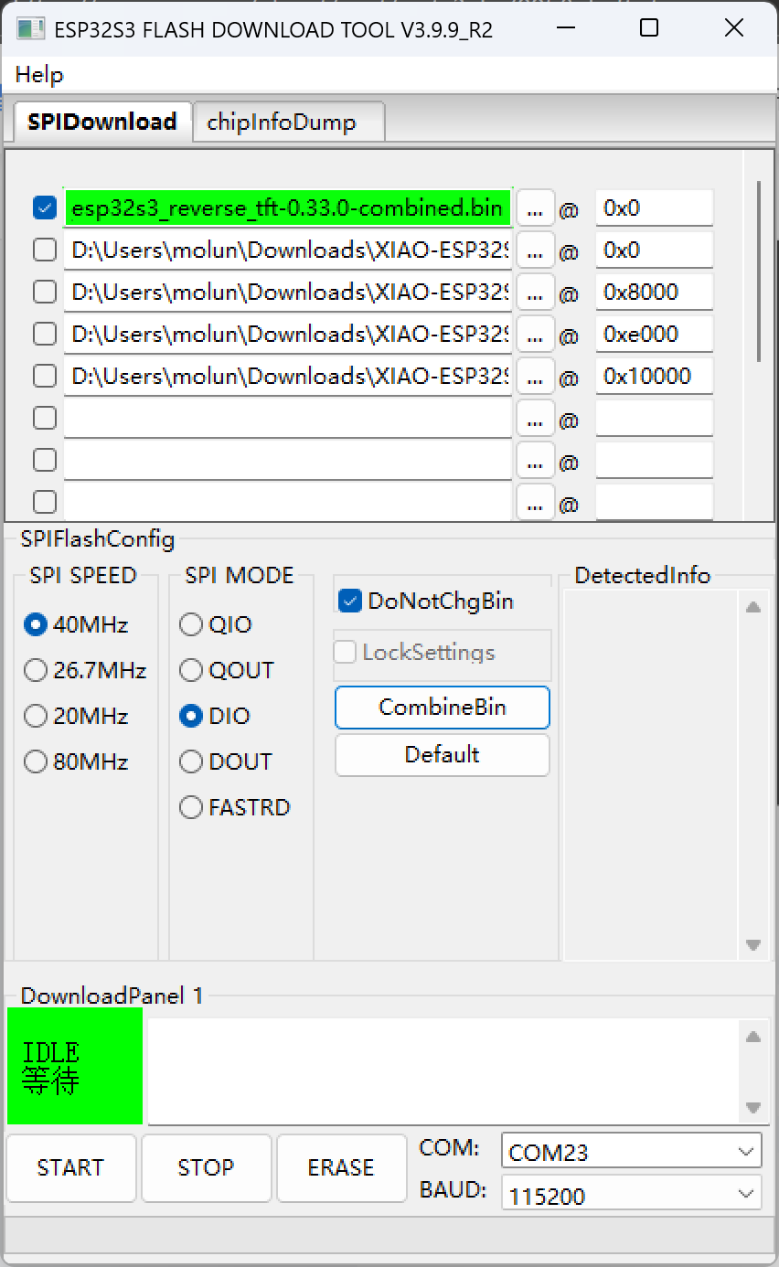
不难看出,实际上使用乐鑫的flash_download_tool工具也是可以完成烧录的。
flash_download_tool烧录

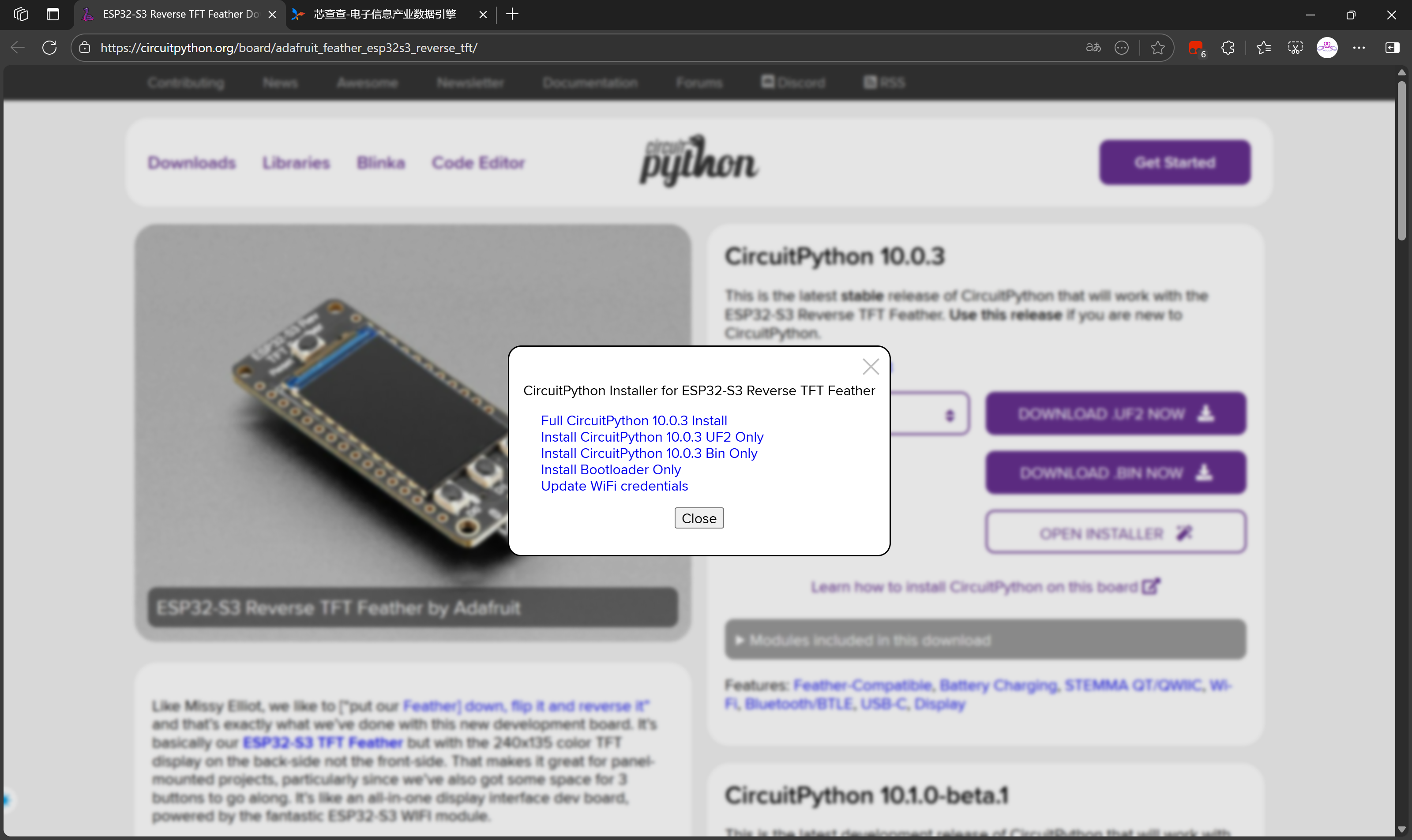
在线一键烧录
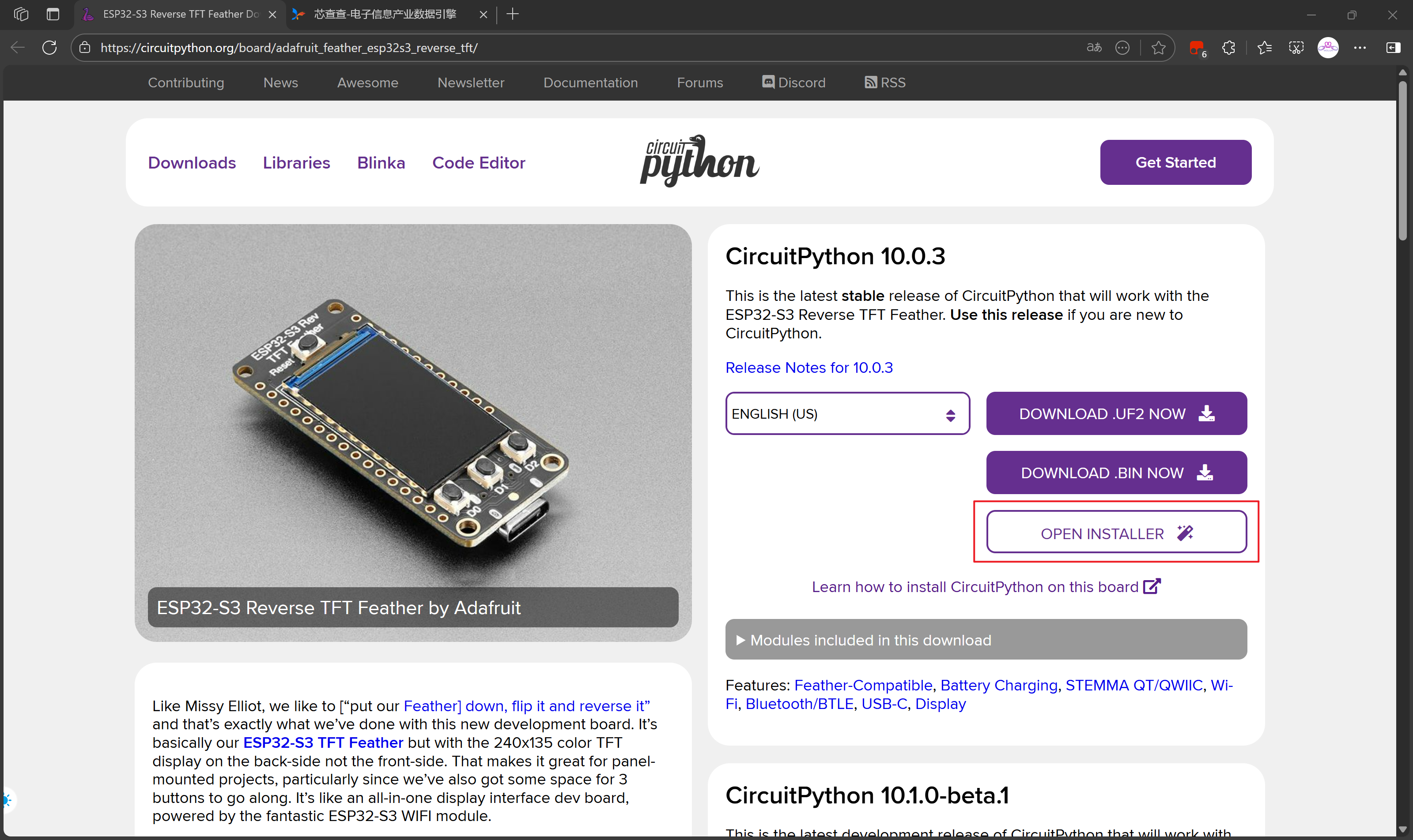
我这里尝试使用在线安装
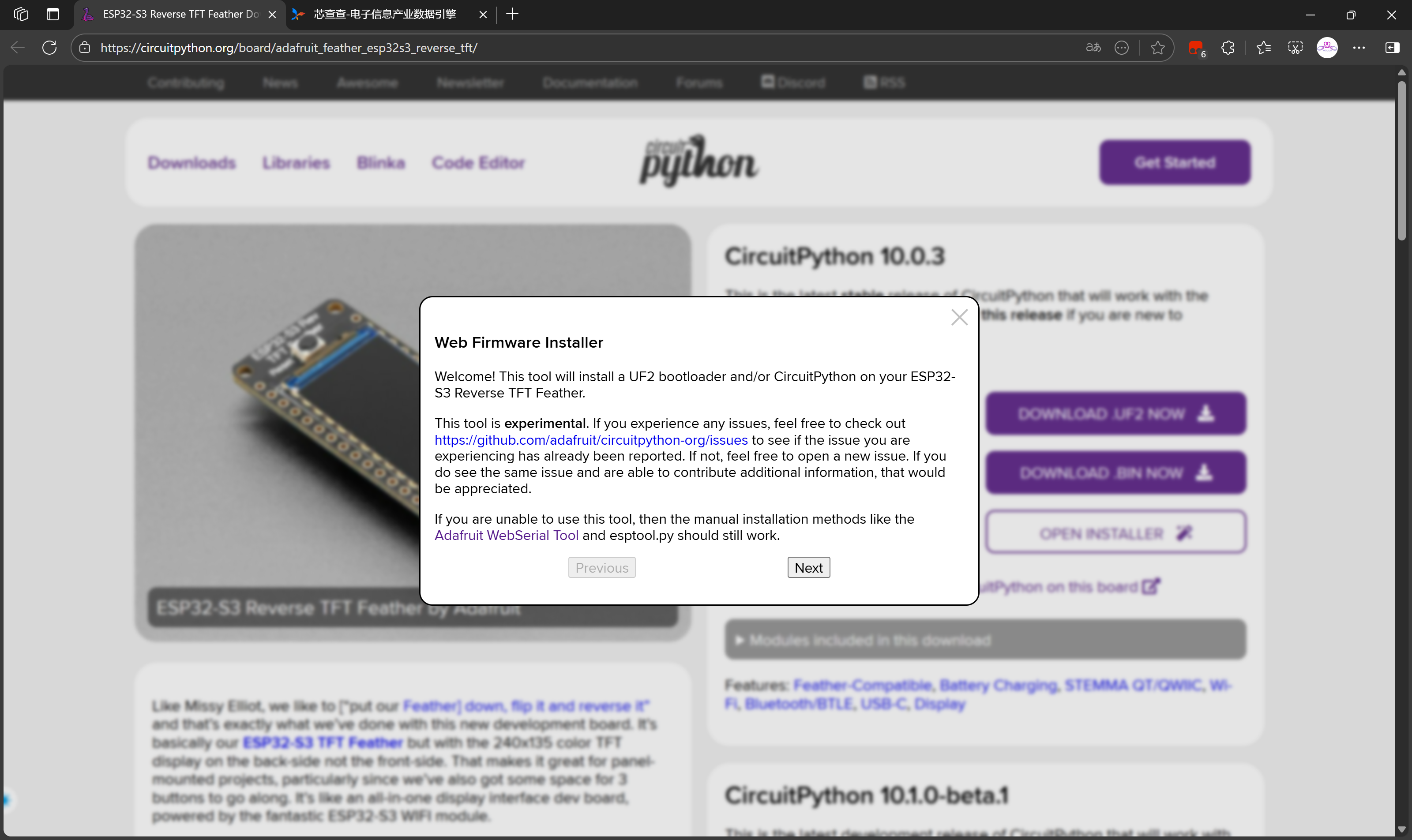
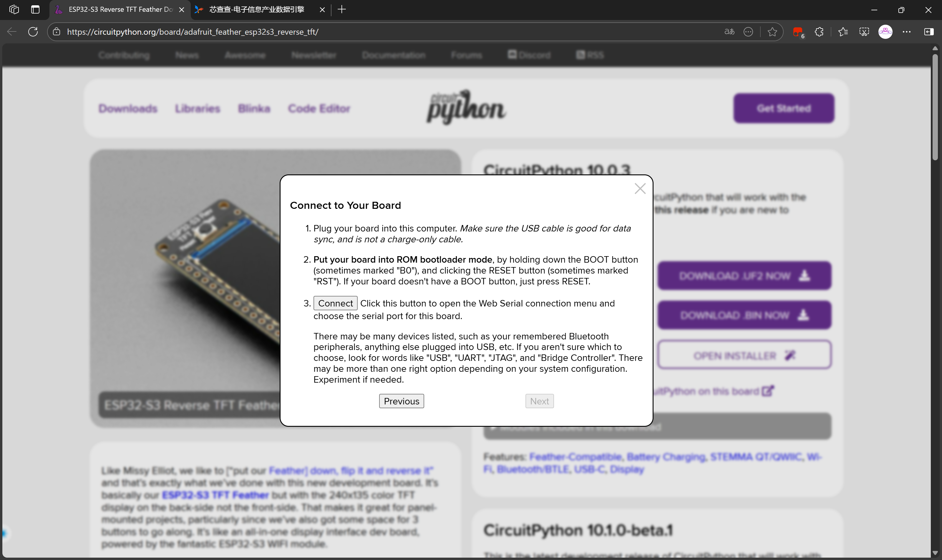
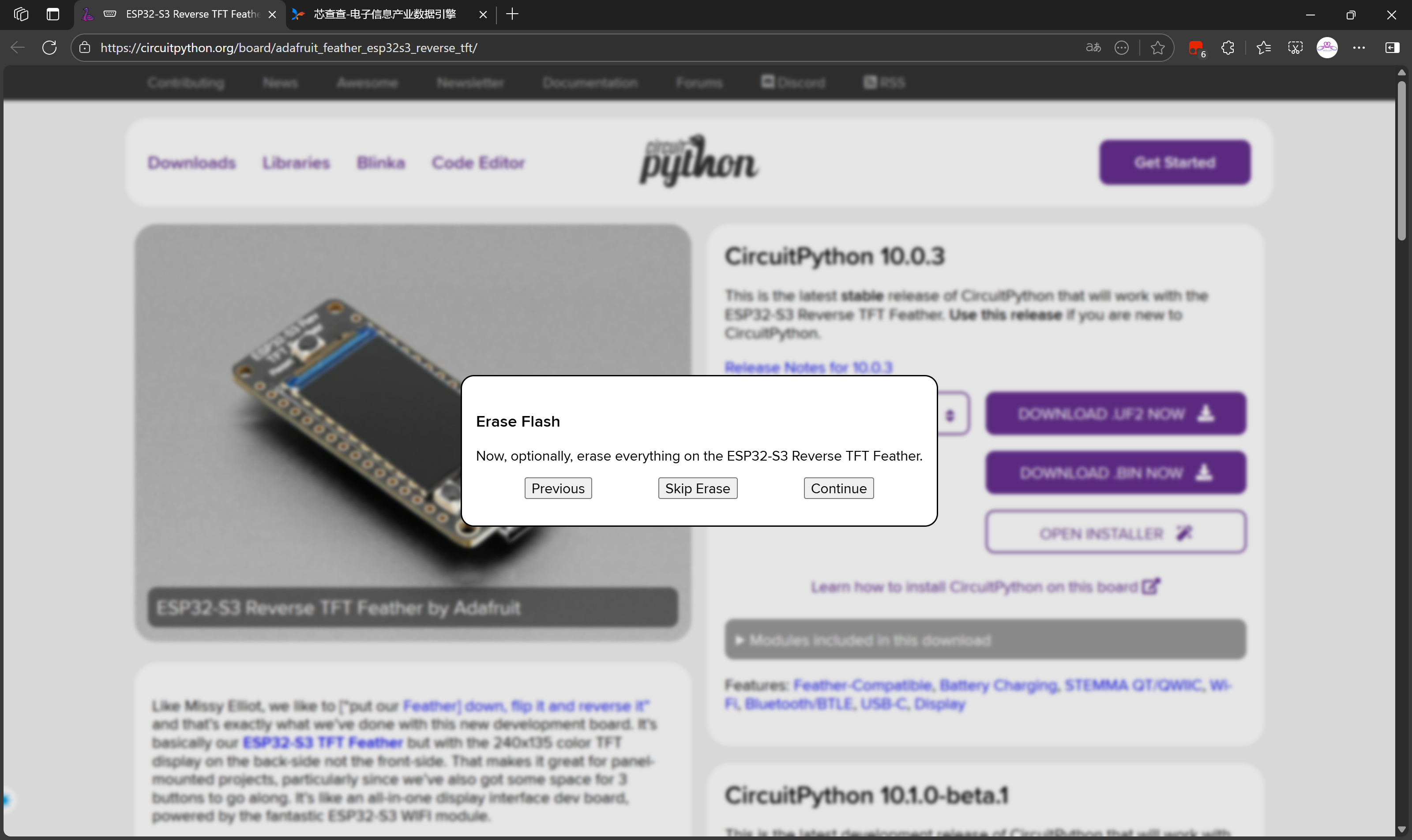

选择Continue继续擦除
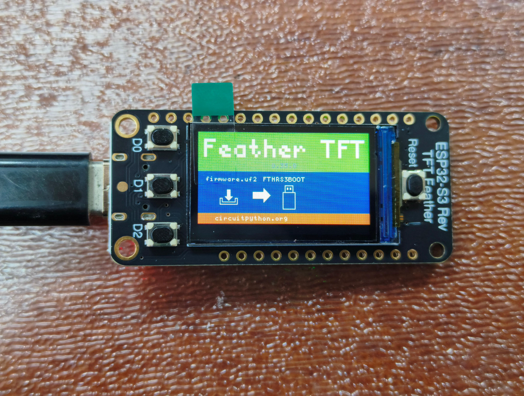
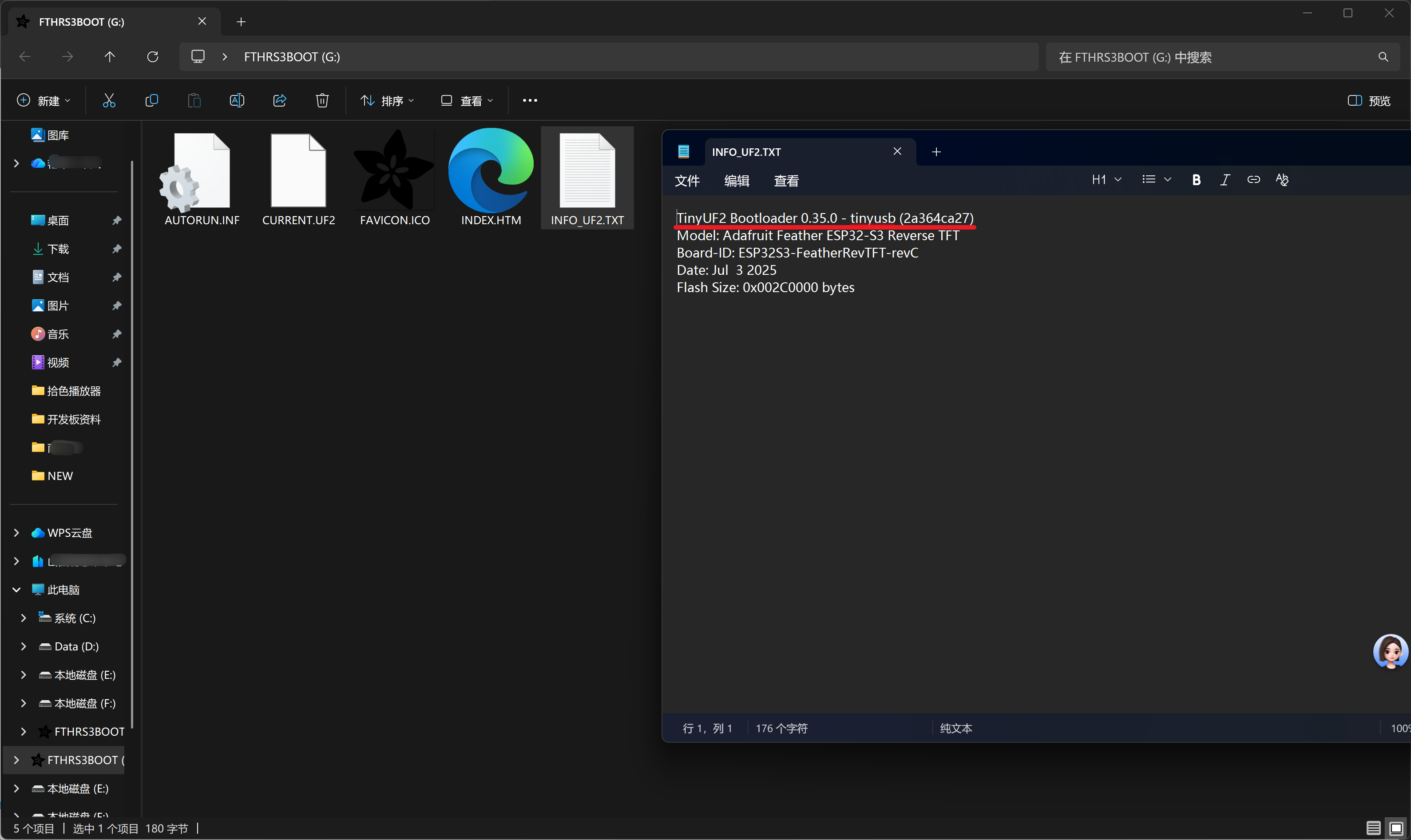
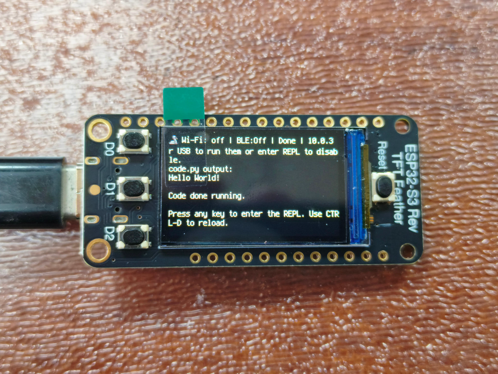
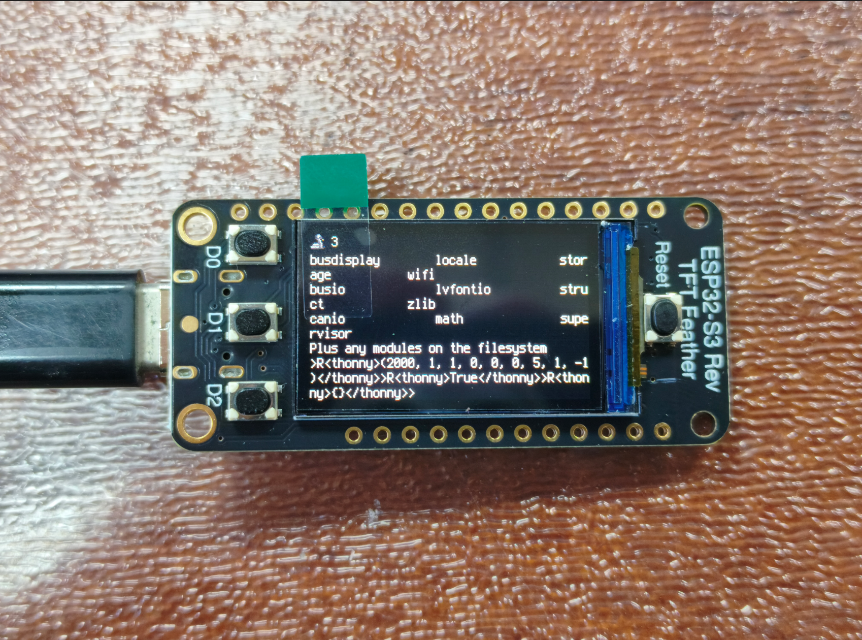
按一次开发板上的Reset按钮,开发板进入如下引导界面,可以看到显示0.35.0版本,可见我们刚刚已经更新成功!
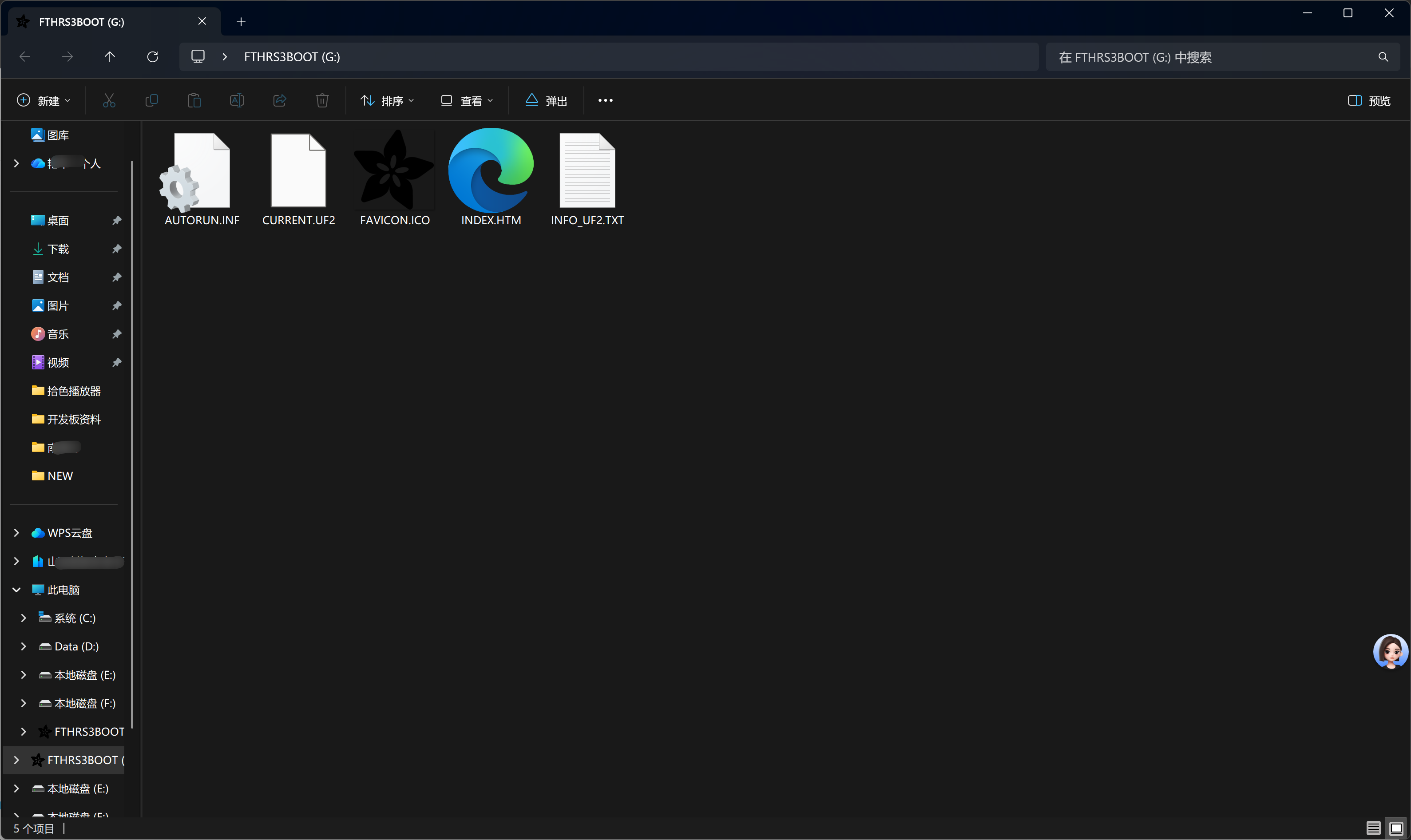
与此同时电脑出现一个名为FTHRS3BOOT的驱动器
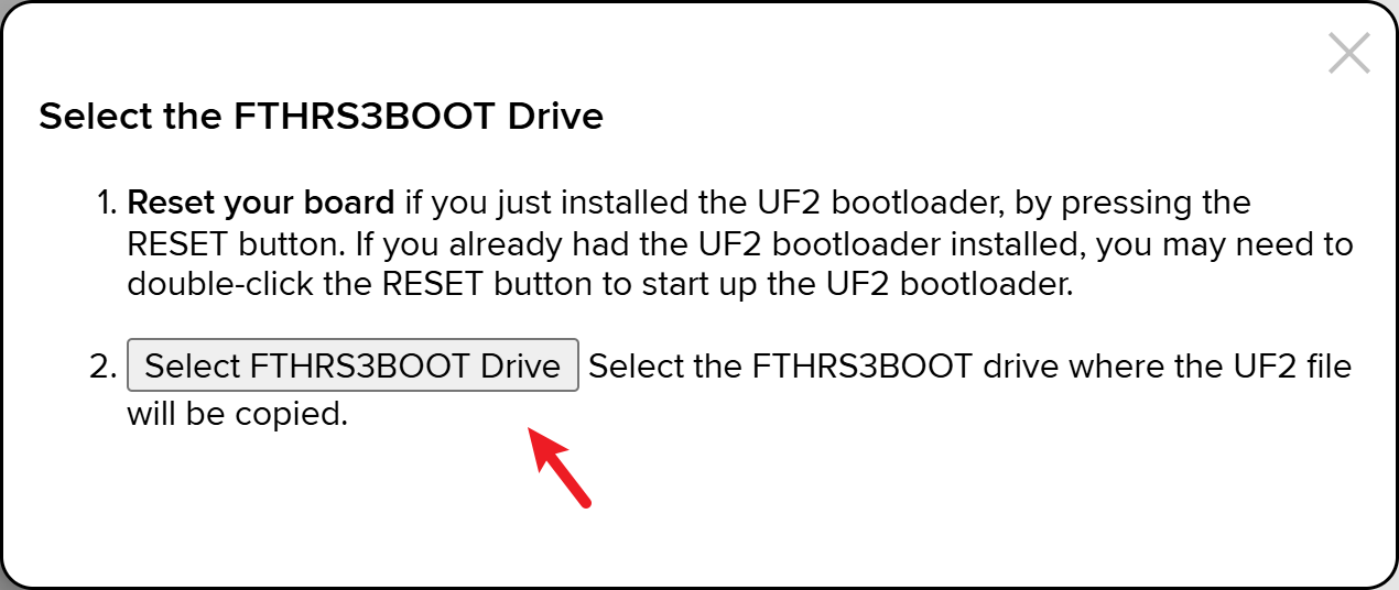
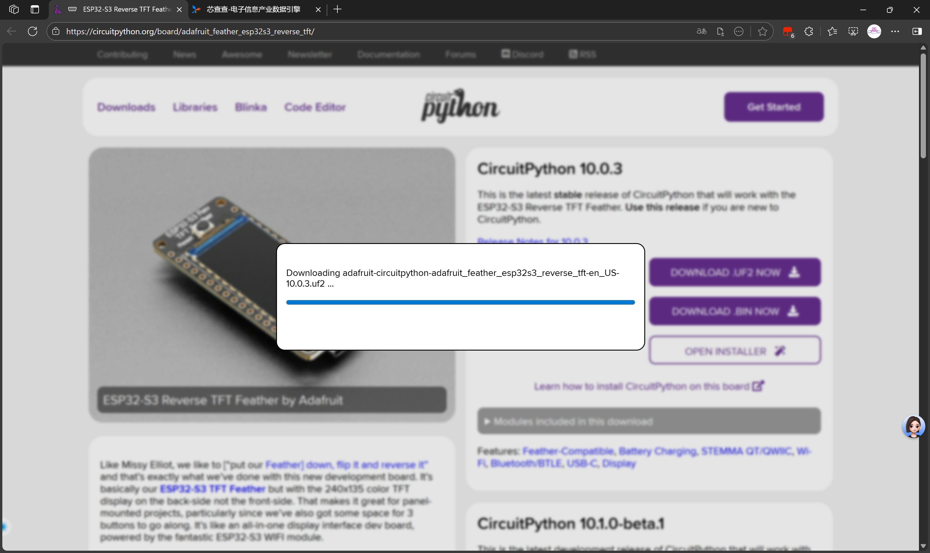
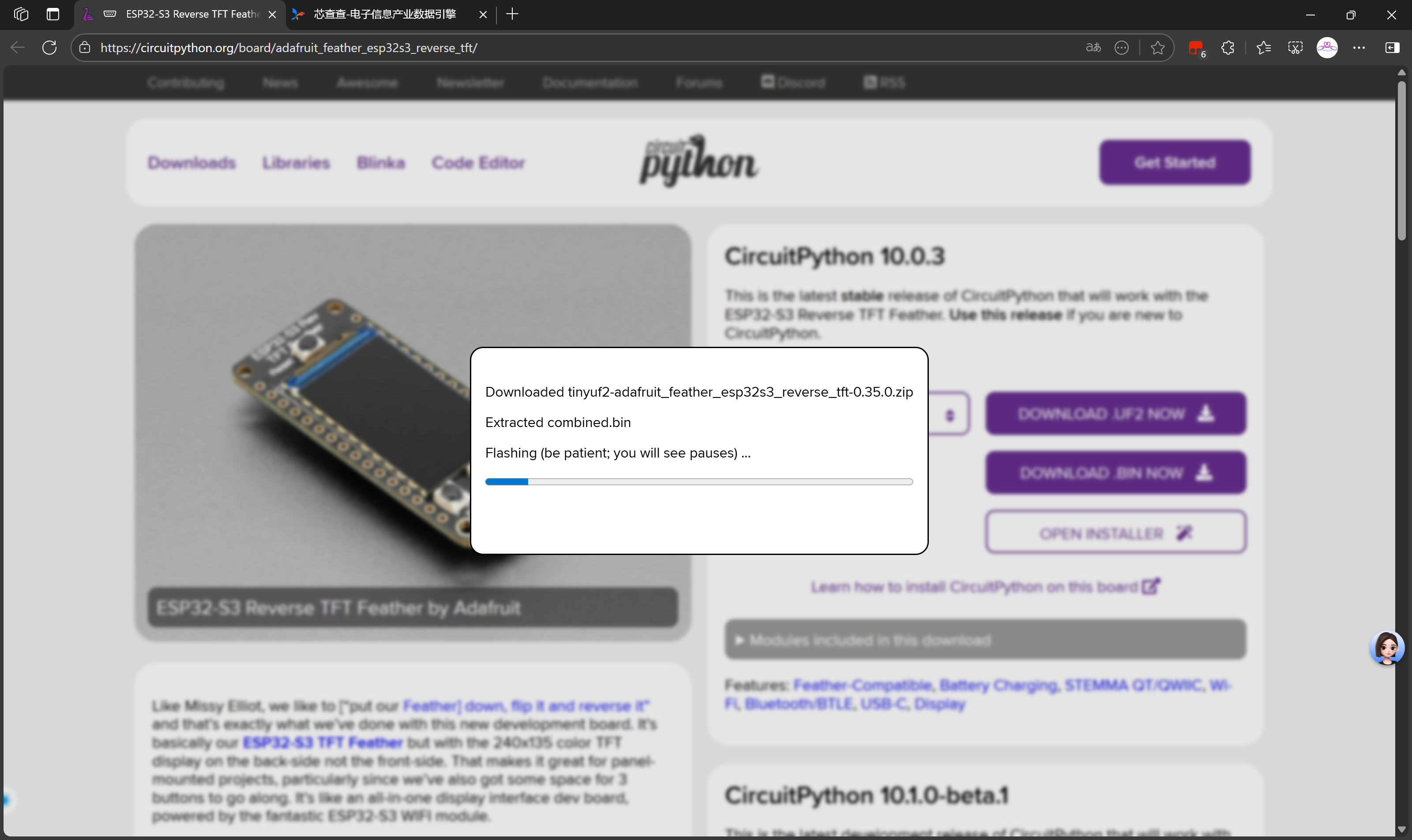
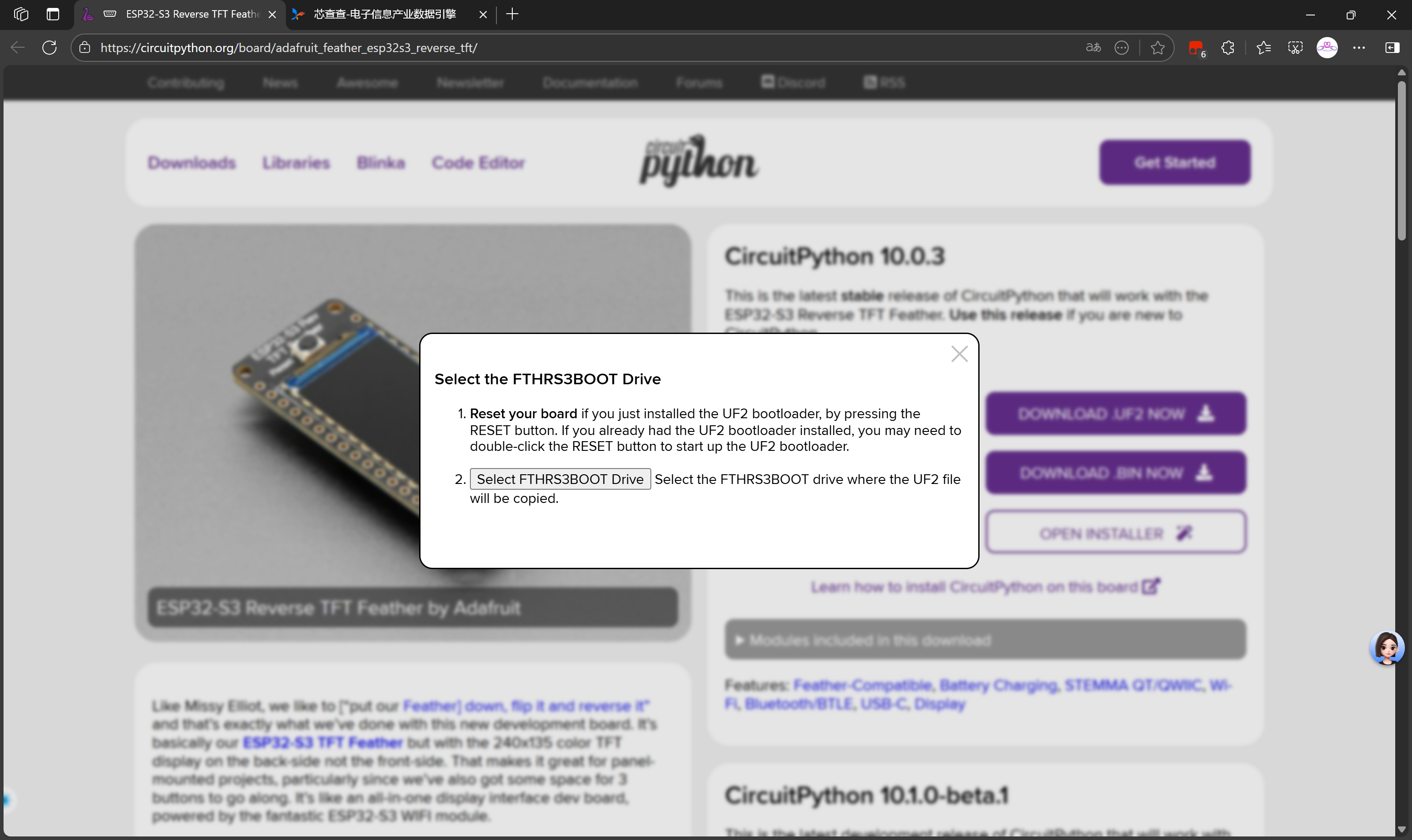
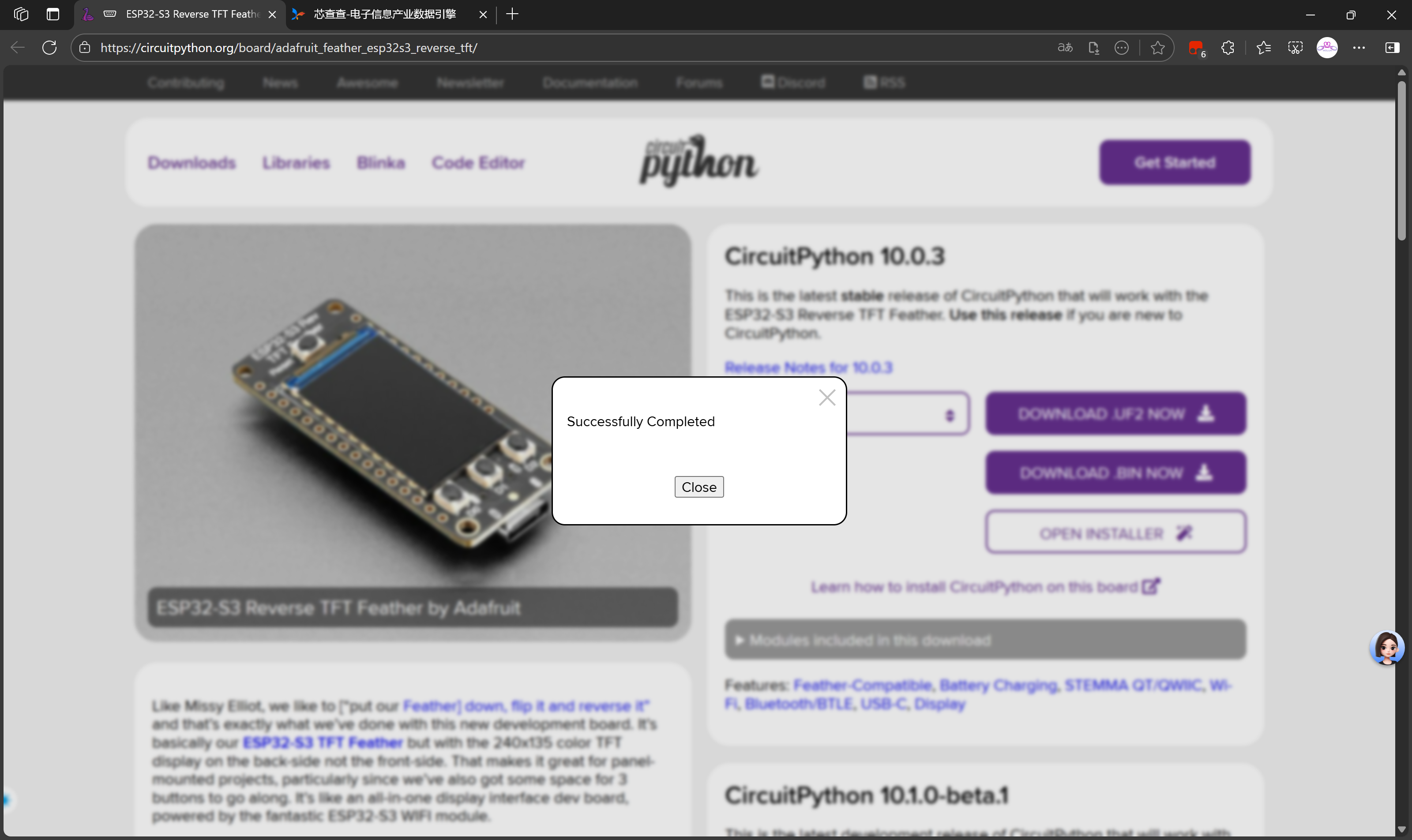
选择后会自动处理下载固件
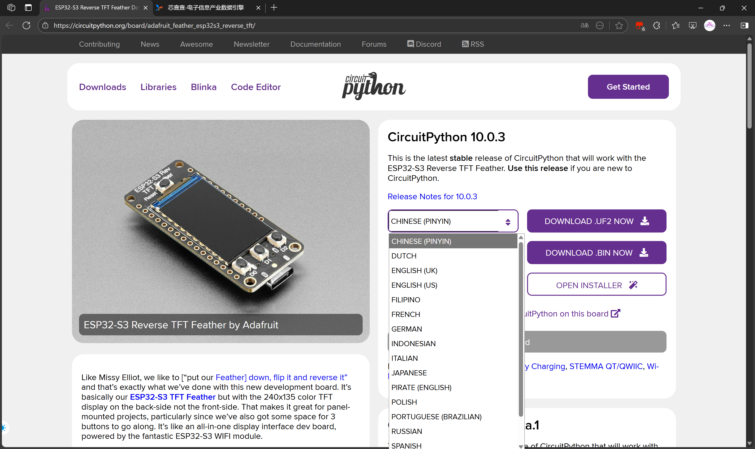
adafruit-circuitpython-adafruit_feather_esp32s3_reverse_tft-en_US-10.0.3.uf2当然我们可以下载其他语言的,比如:
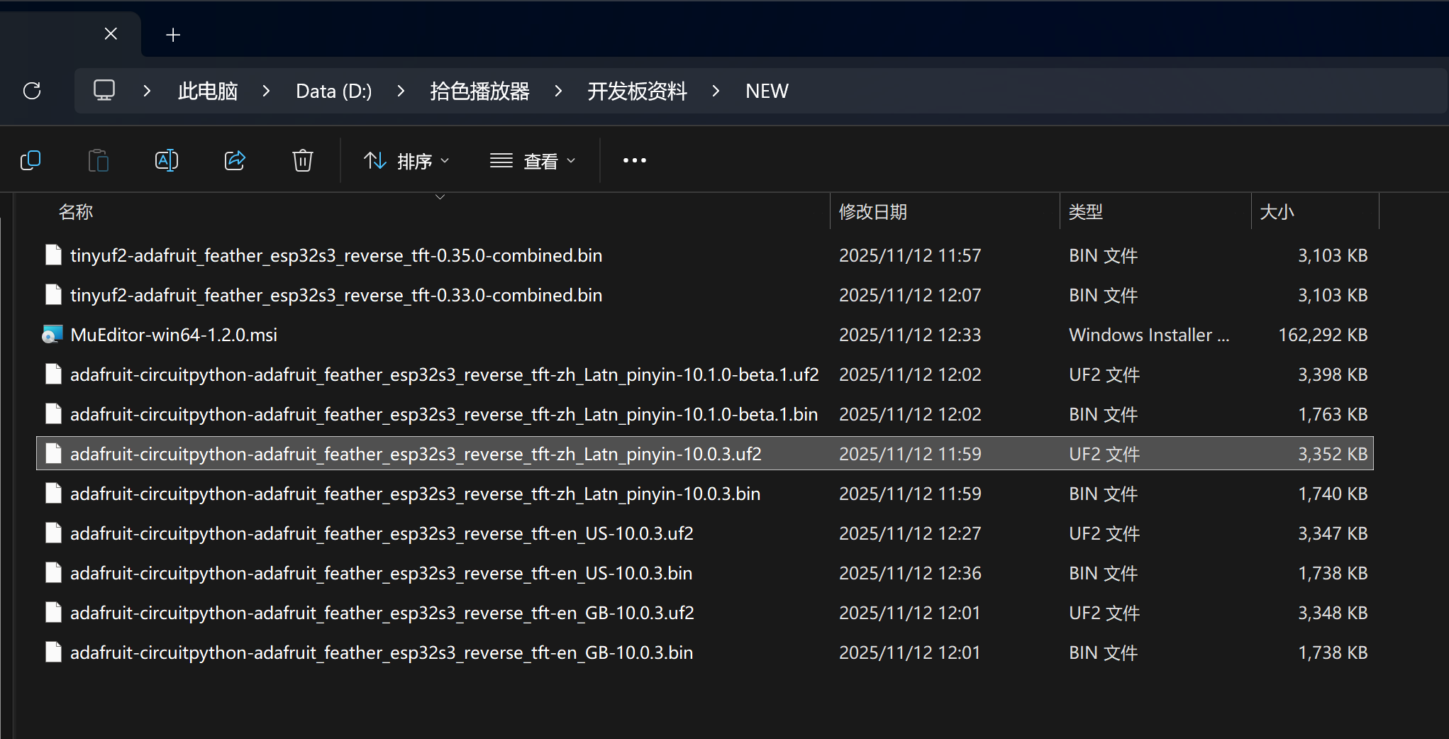
adafruit-circuitpython-adafruit_feather_esp32s3_reverse_tft-zh_Latn_pinyin-10.0.3.uf2bin固件可以烧录乐鑫的烧录工具进行烧录,而uf2固件只需要下载后拖动到FTHRS3BOOT驱动器即可完成固件更新。
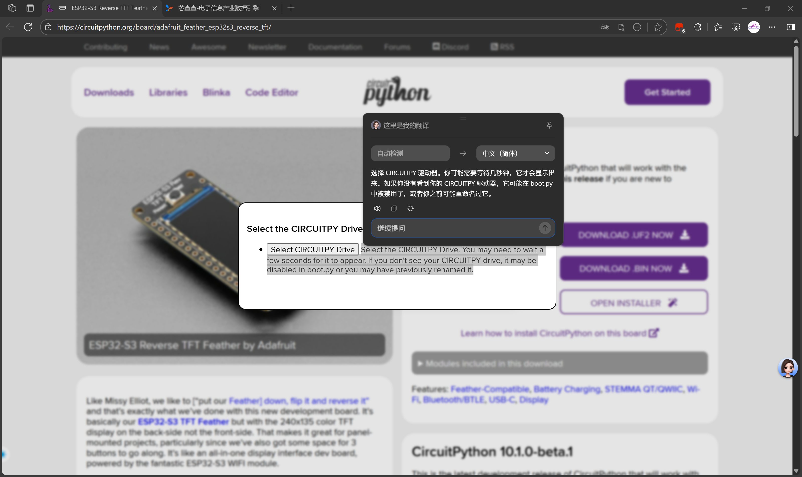
这里给大家安利下豆包这个插件,选取文字后即可进行翻译和解释,简直不要太方便,有啥看不懂的点一下就明白了!
说明:
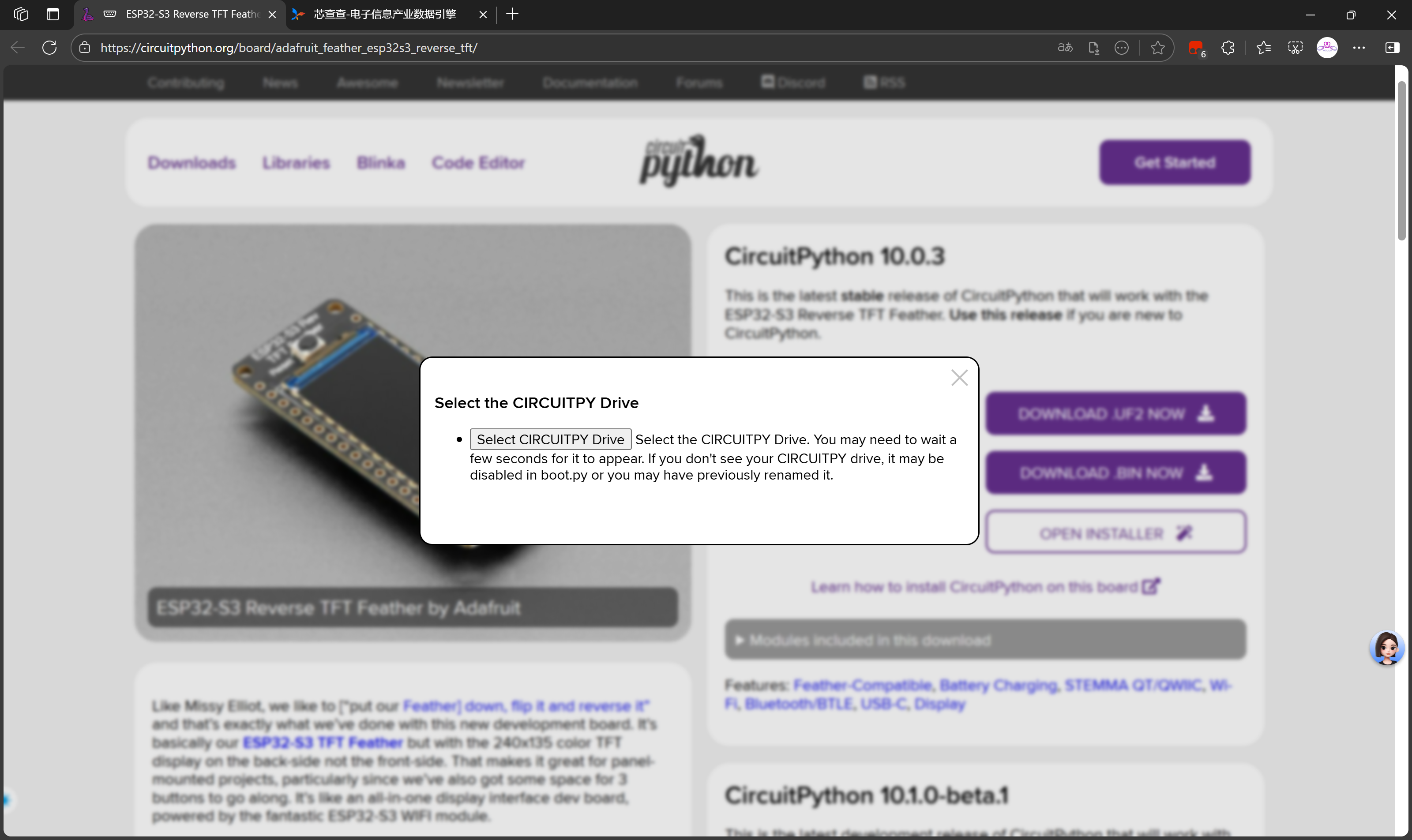
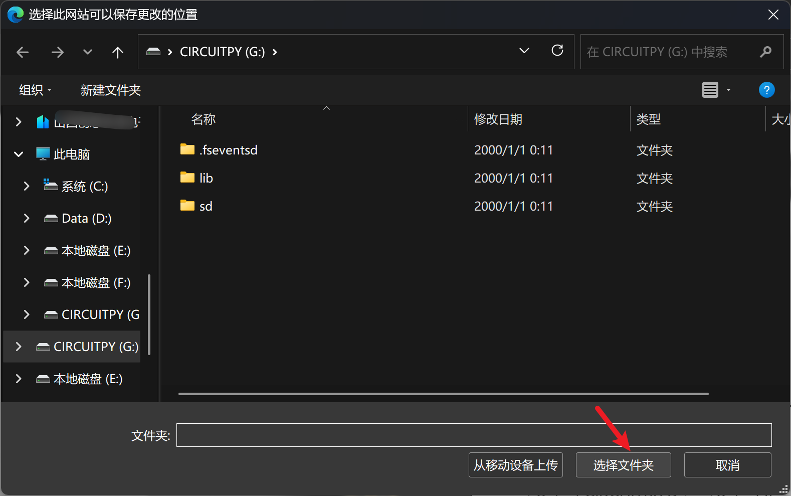
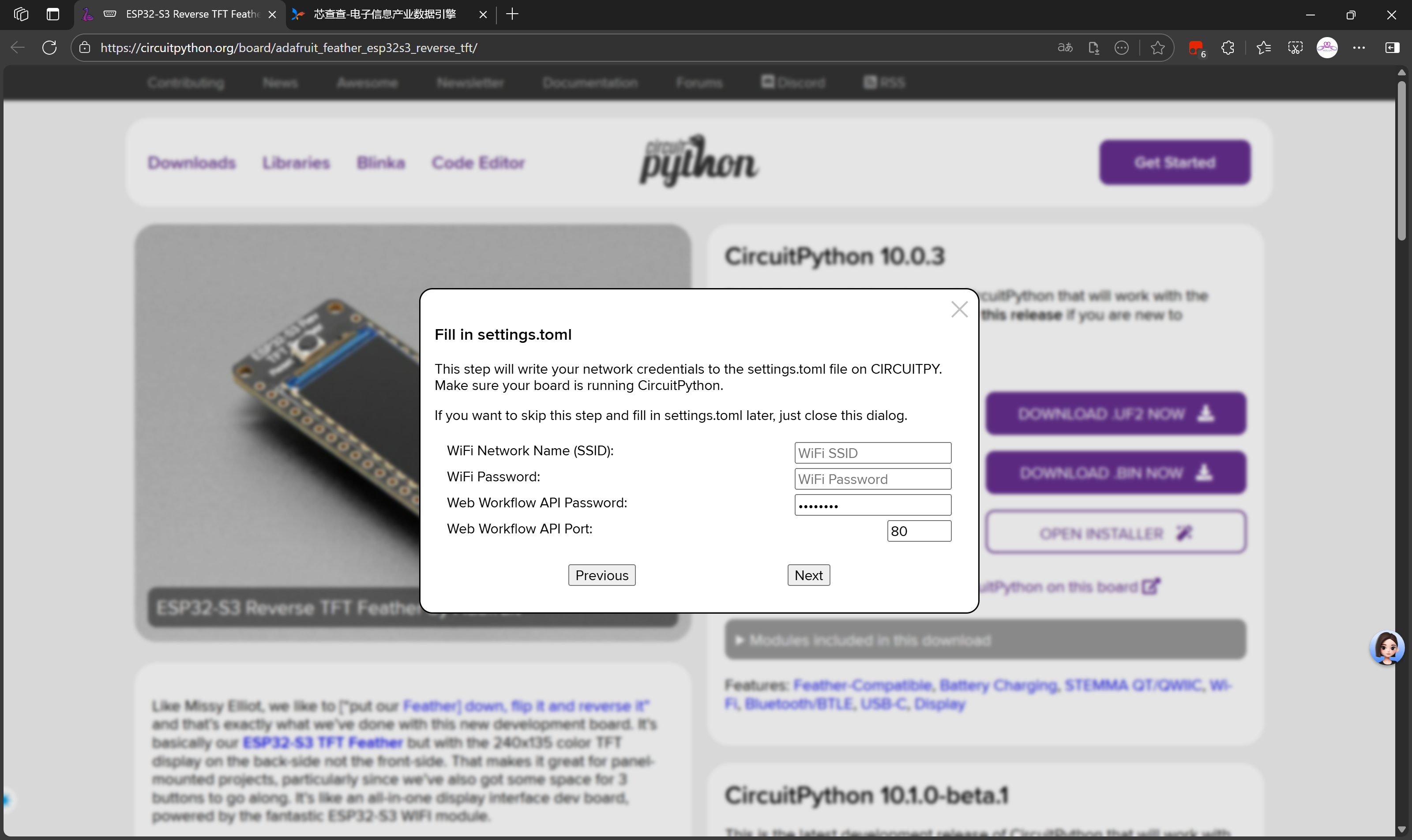
这是一个 CircuitPython 设备的网络配置界面,用于设置设备连接 WiFi 网络。settings.toml 是 CircuitPython 中用于存储配置参数的文件,包括网络凭据、API 设置等。填写完成后,设备将能够连接到指定的 WiFi 网络,并启用 Web 工作流功能。

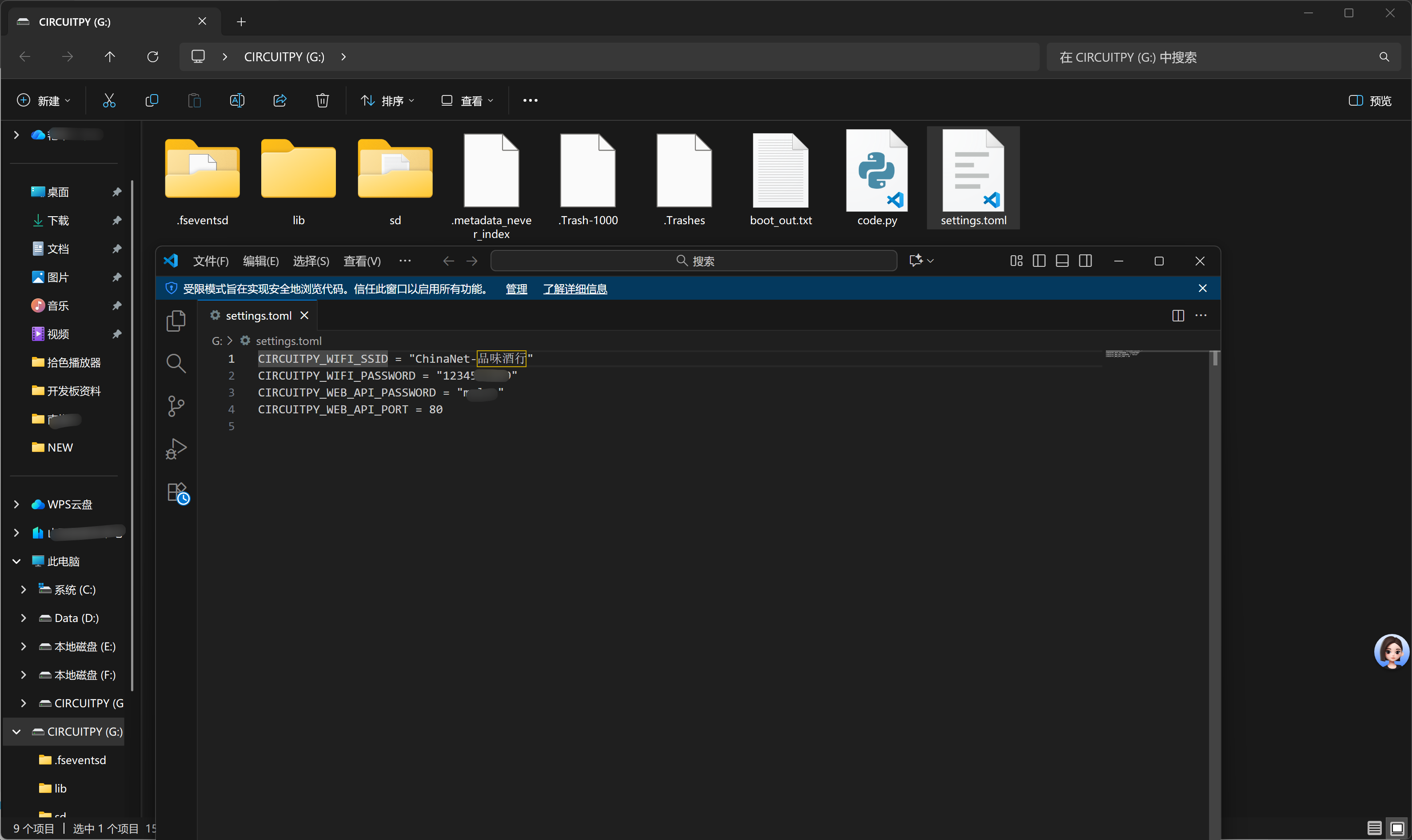
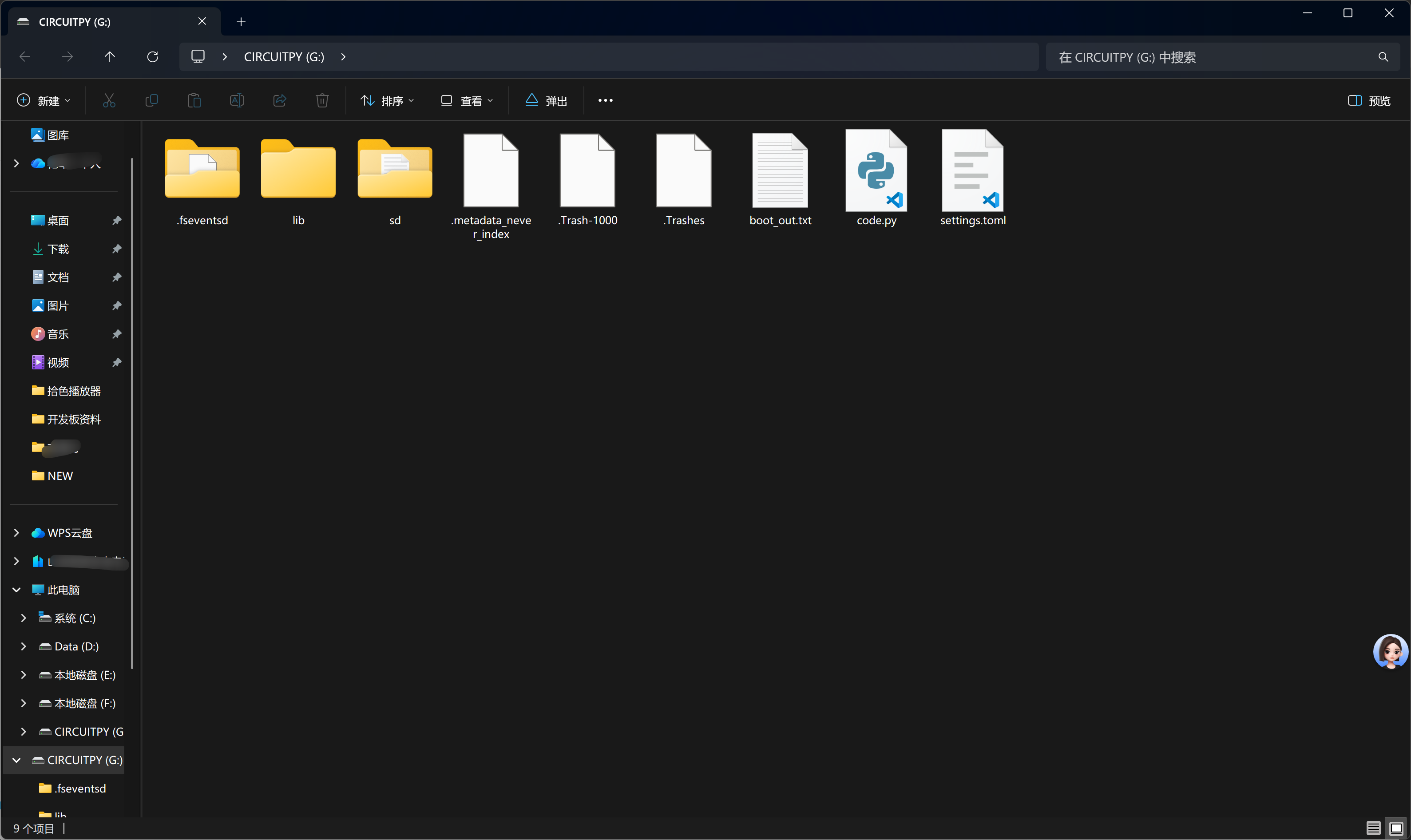
刚刚网页端的设置,实际上是给settings.toml中写入配置信息。
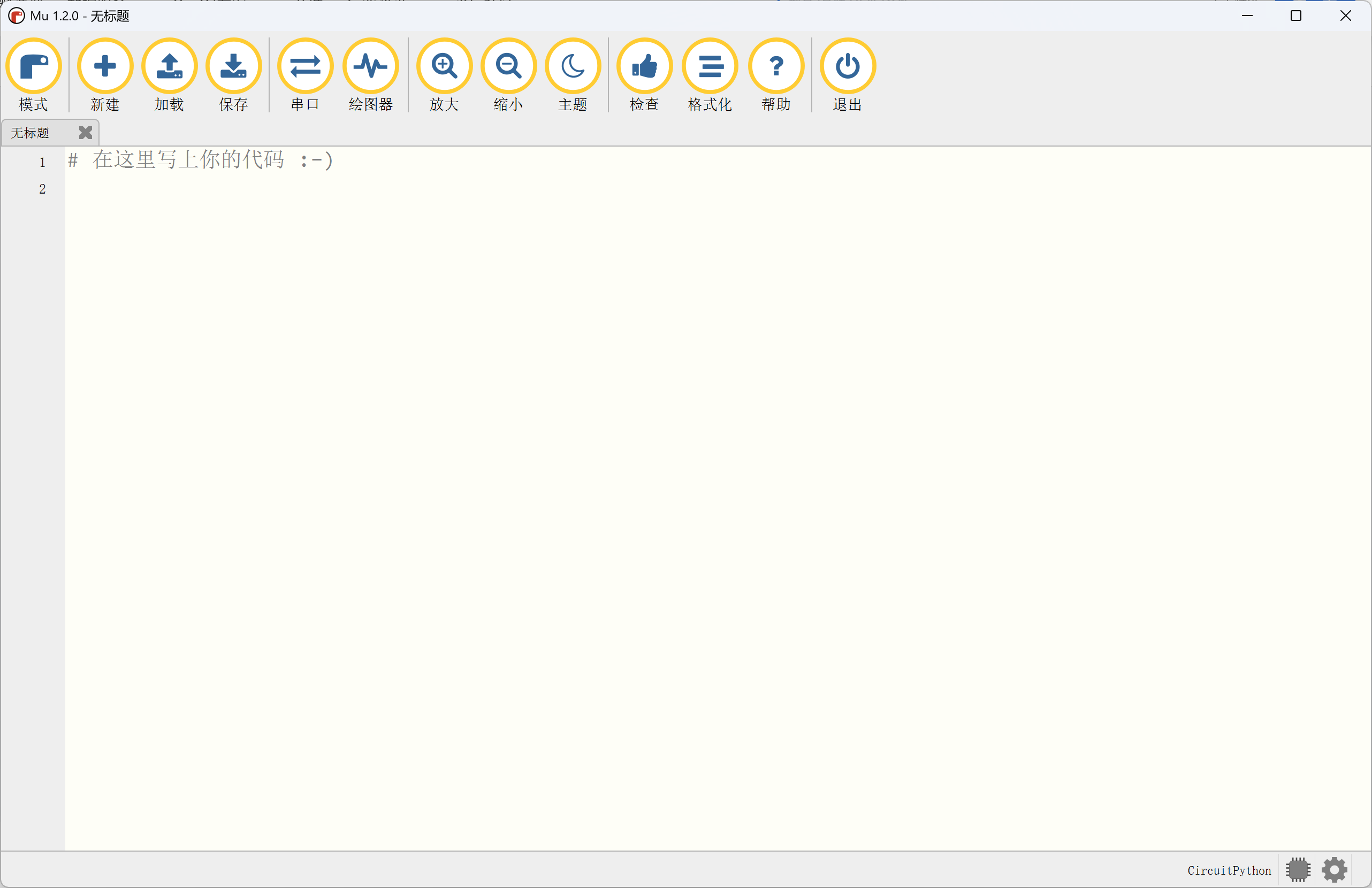
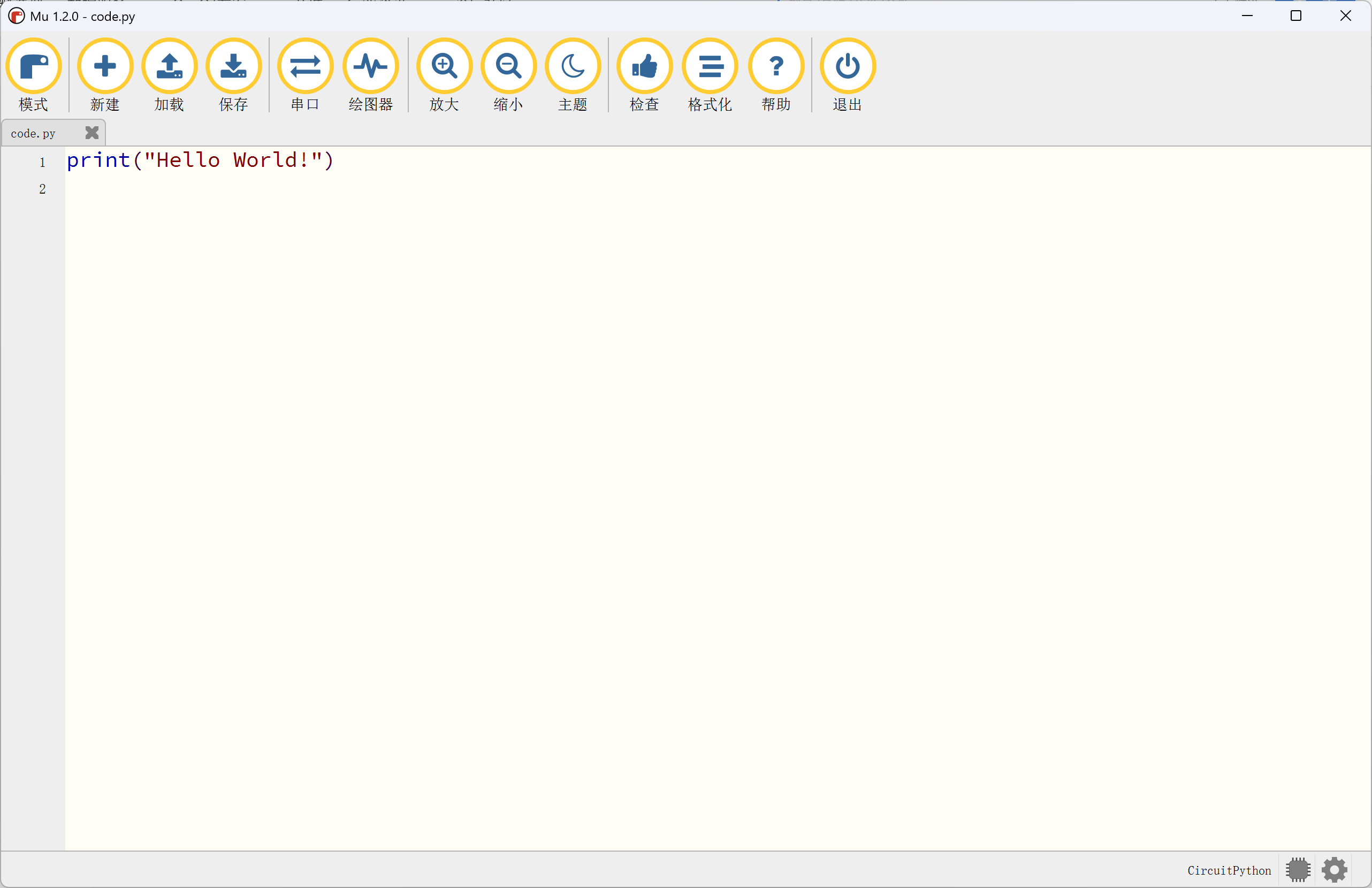
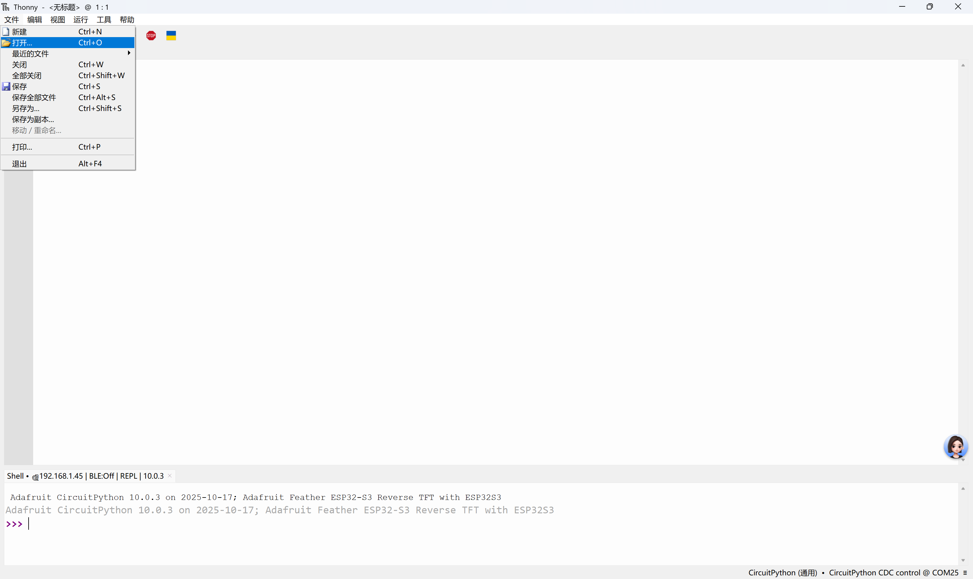
Mu编辑器(该项目目前已停更)
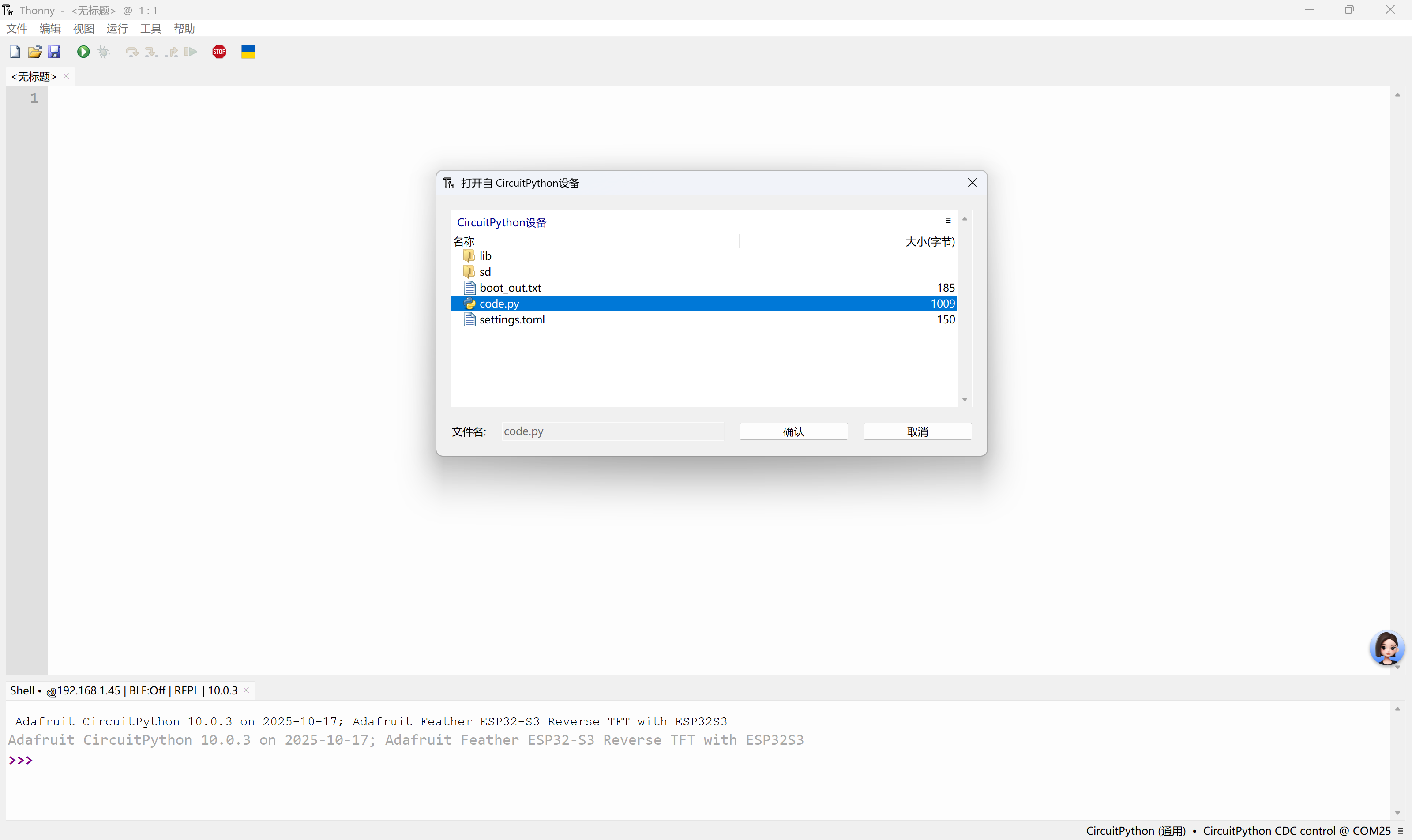
Thonny编辑器
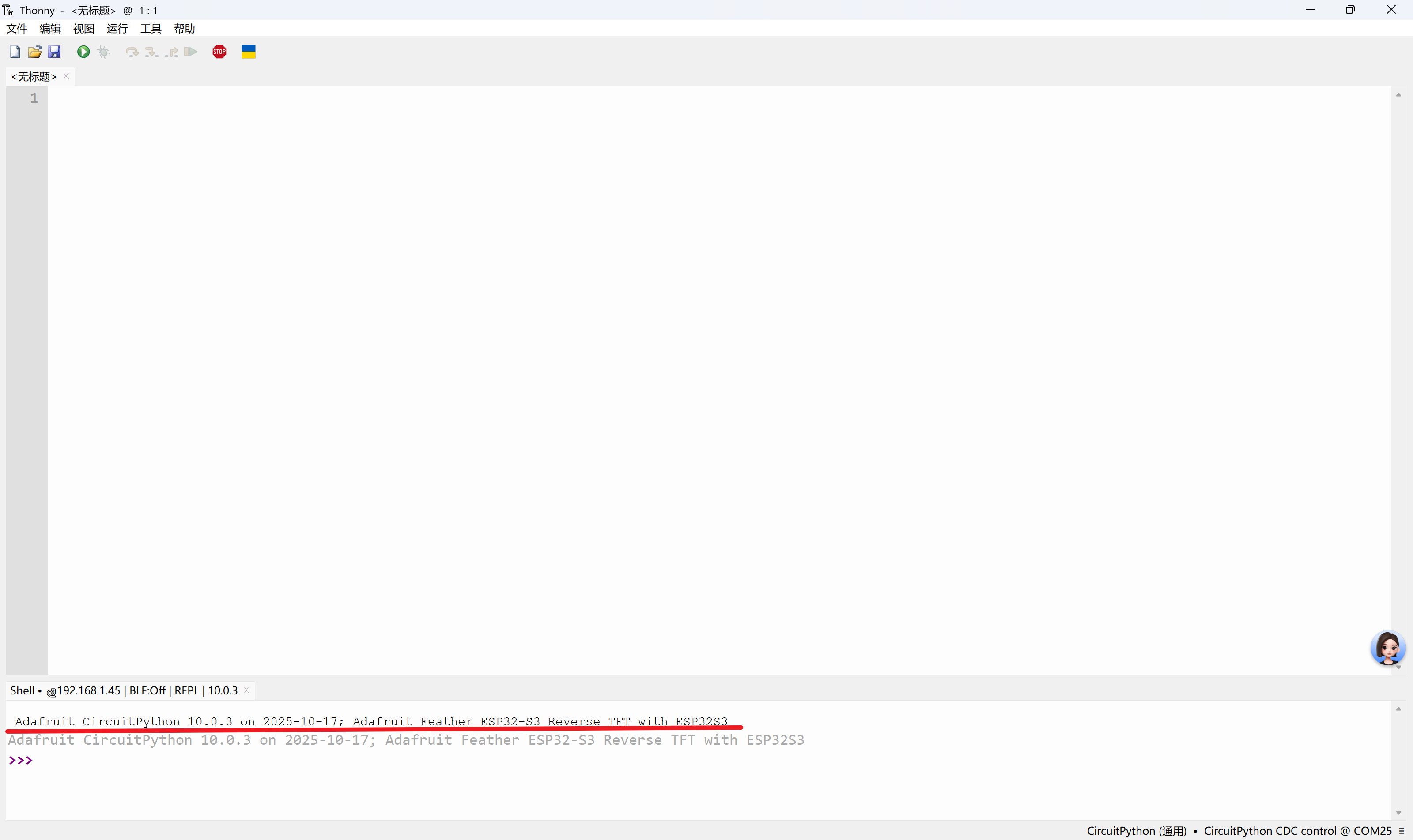
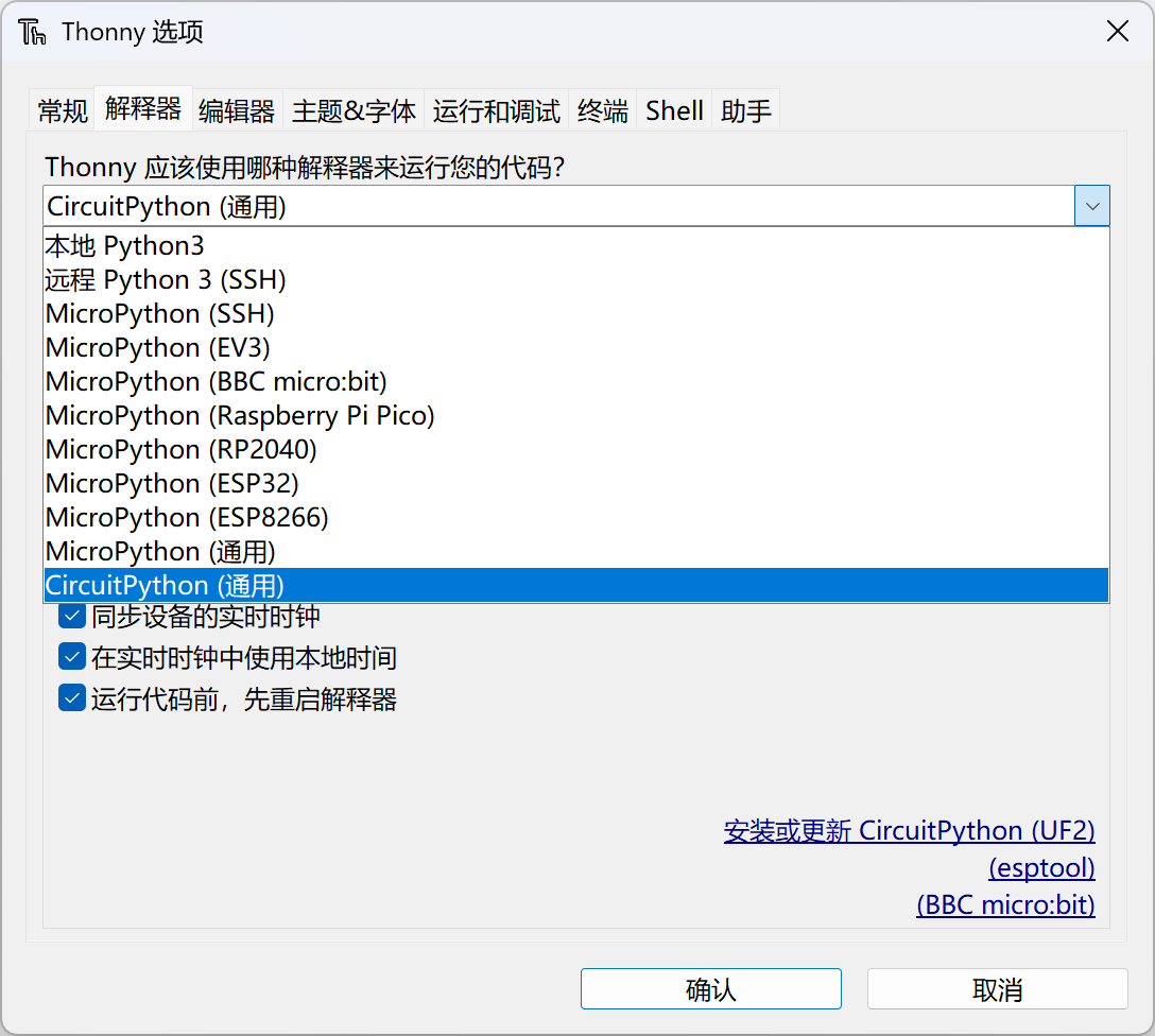
Mu和Thonny都是支持CircuitPython的。
使用CircuitPython时需要安装对应版本的库文件
CircuitPython Libraries:https://circuitpython.org/libraries
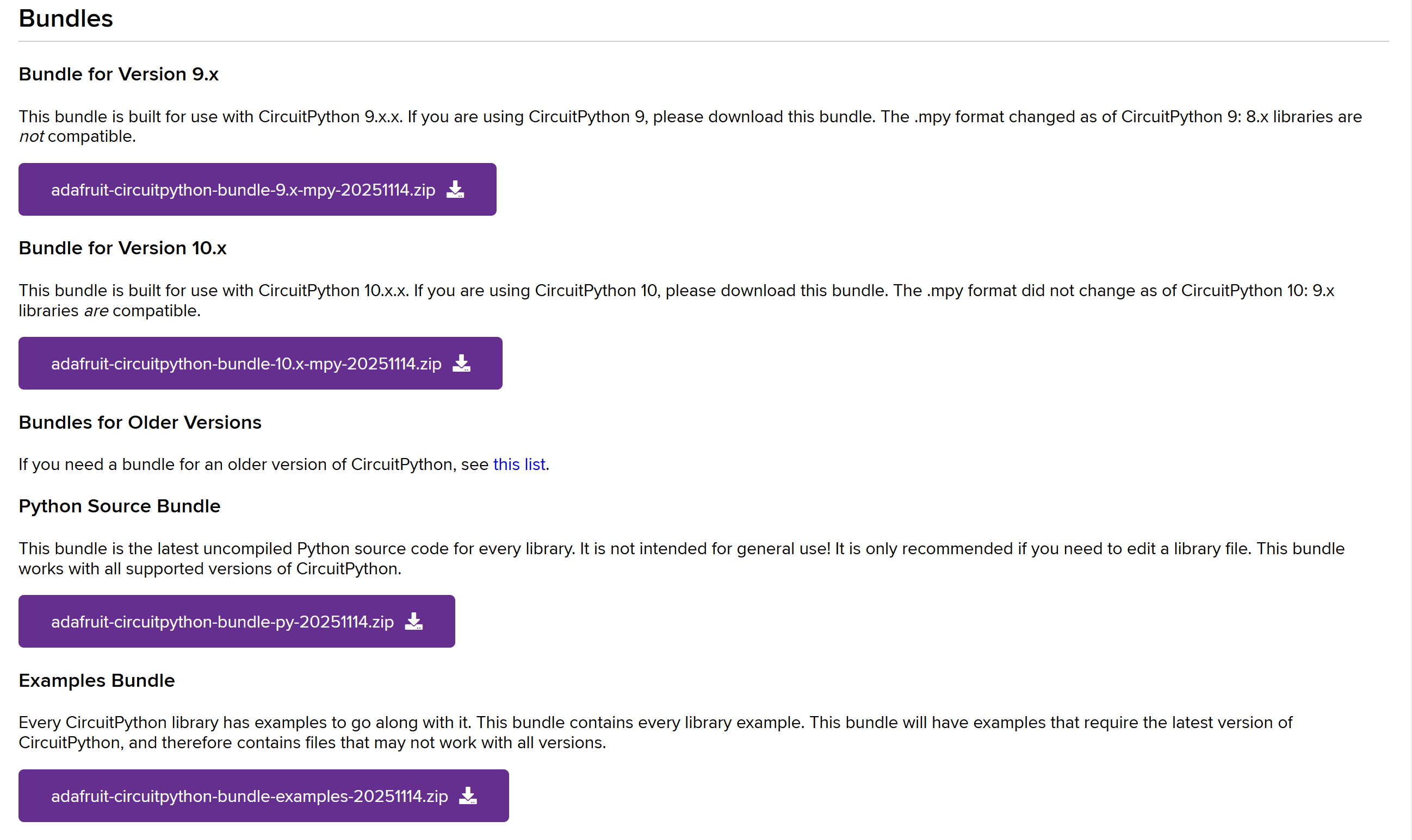
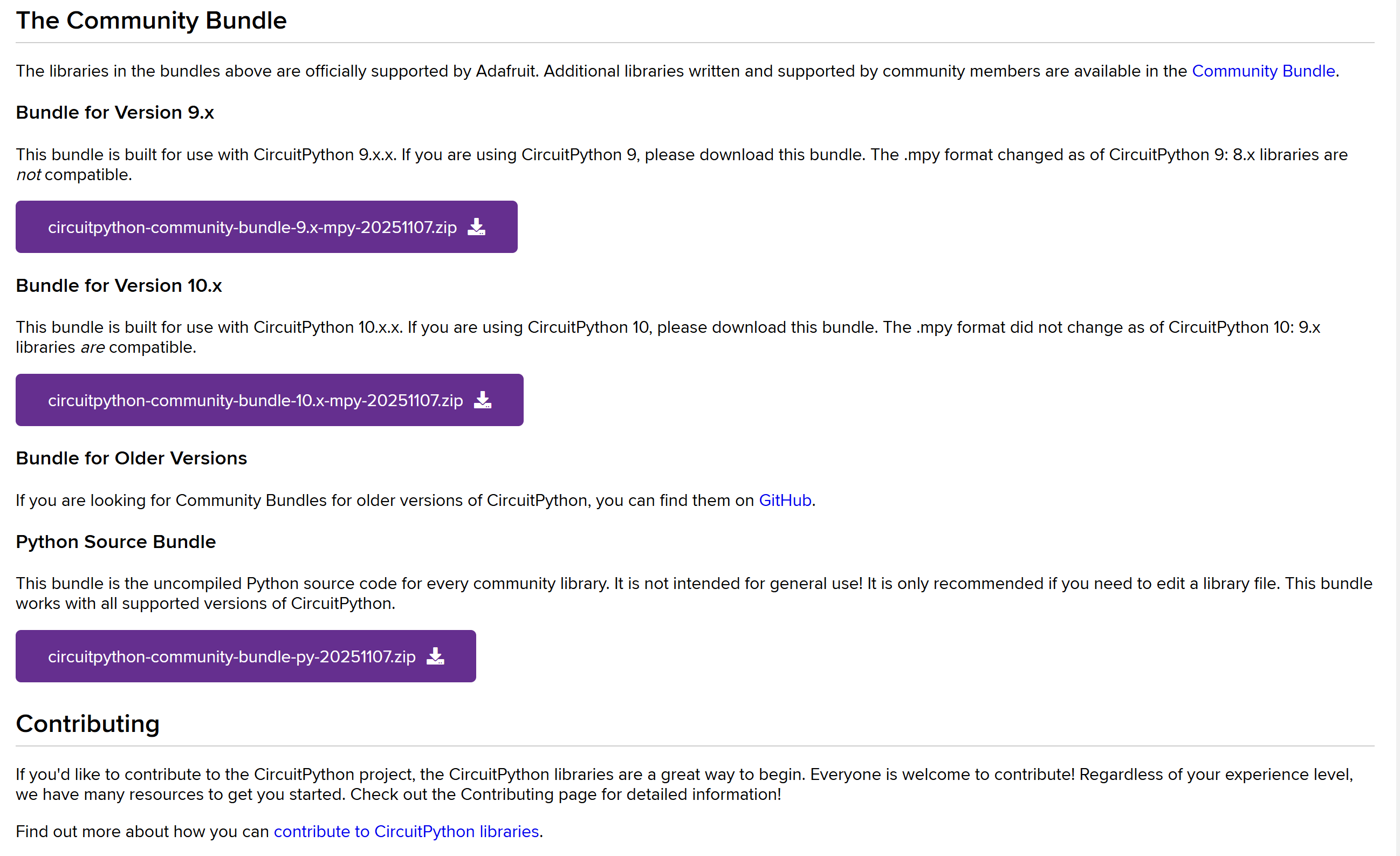
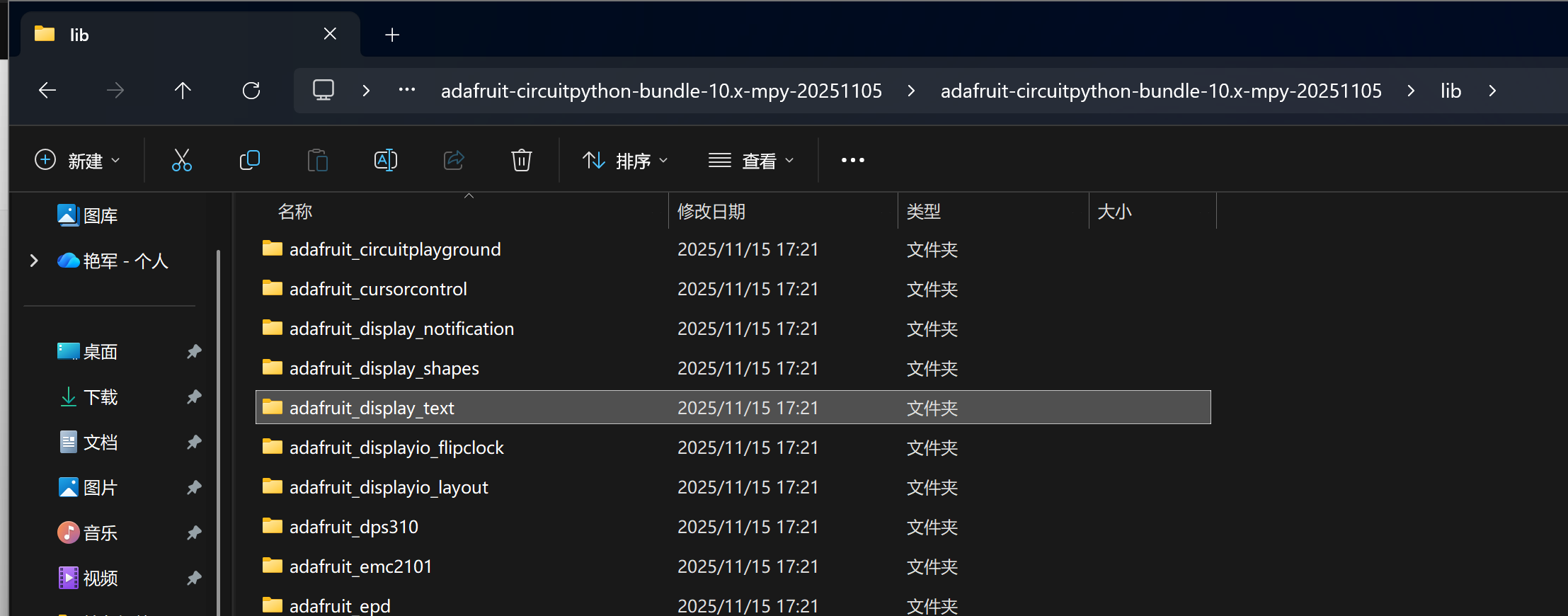
由于我们使用的CircuitPython 10.0.3,因此需要下载10.x版本的库,上方有官方库和社区库,这点类似于Arduino。
adafruit-circuitpython-bundle-10.x-mpy-20251114.zip
circuitpython-community-bundle-10.x-mpy-20251107.zip
# CircuitPython库使用要点概述
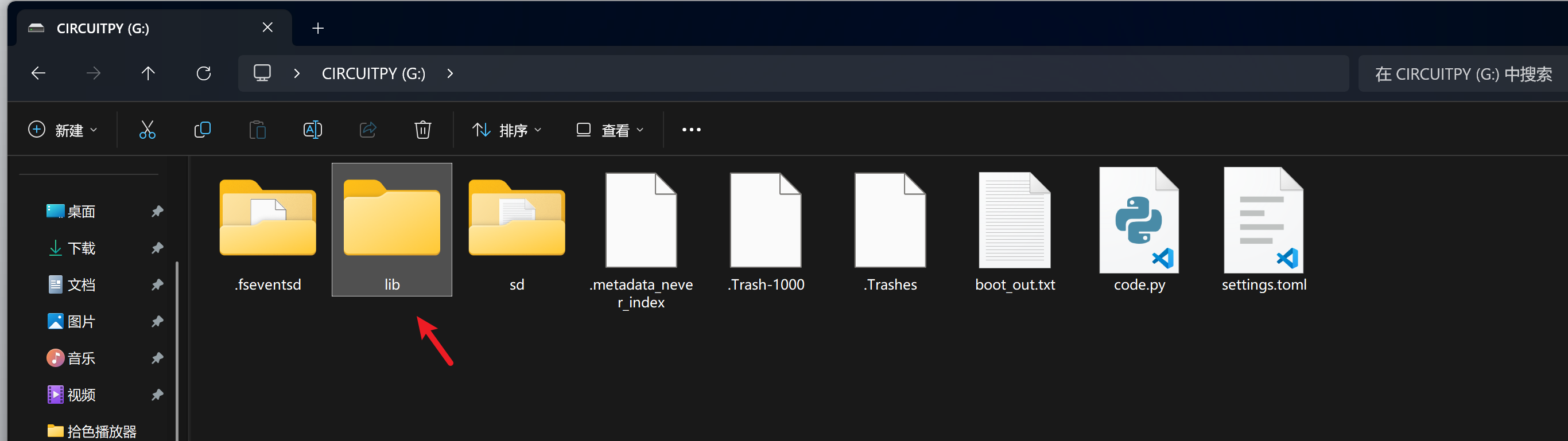
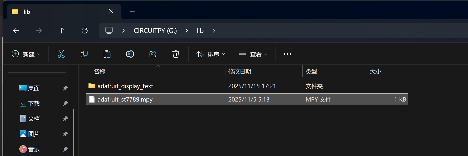
1. **基本运行机制**:CircuitPython库的工作模式与常规Python模块并无二致,Python相关文档是极为重要的参考资料。通常情况下,库文件可放置于 `lib` 目录中,此目录属于Python路径的组成部分。
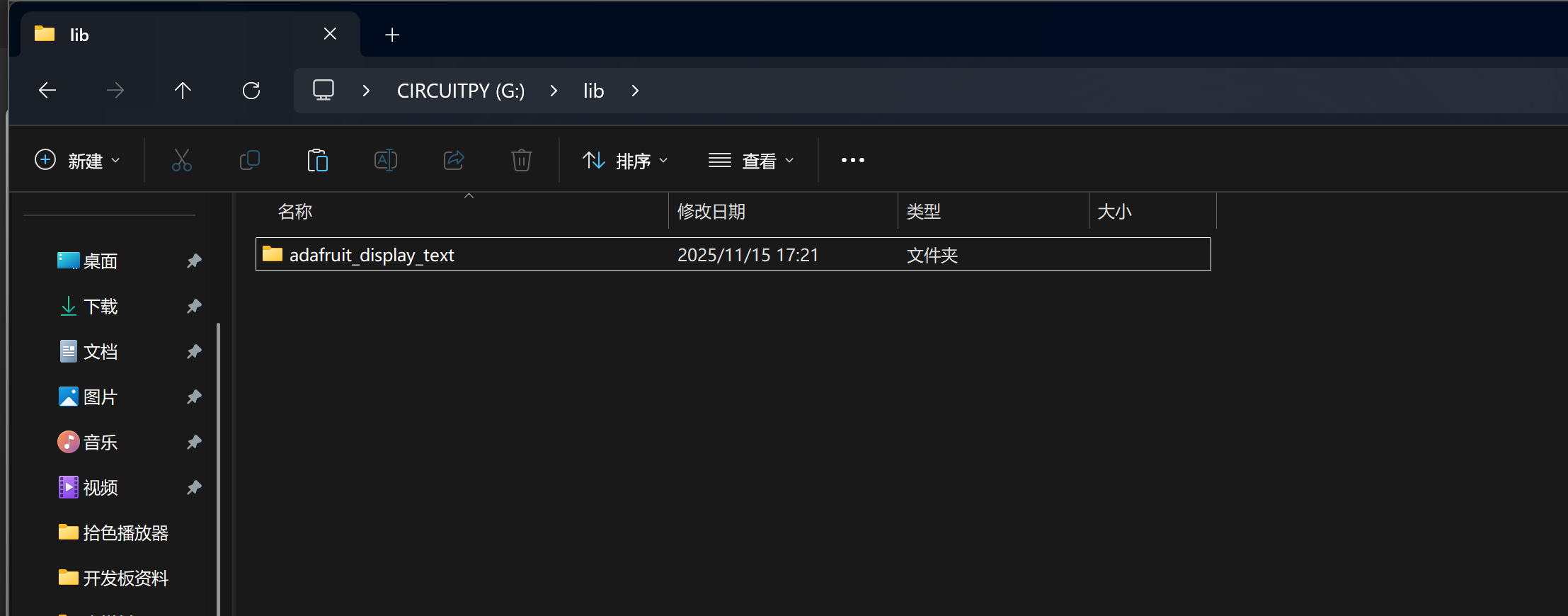
2. **使用的必要条件**:该库并非开发板内置,在使用之前,需将其复制至CIRCUITPY驱动器方可调用。借助库捆绑包(library bundle)可有效简化这一操作流程。
3. **优化版本说明**:GitHub上提供的库捆绑包以及库发布版本中,包含以 `.mpy` 格式呈现的优化库。此类优化库不仅占用的存储空间相对较少,而且在加载过程中,内存占用也更为低廉。
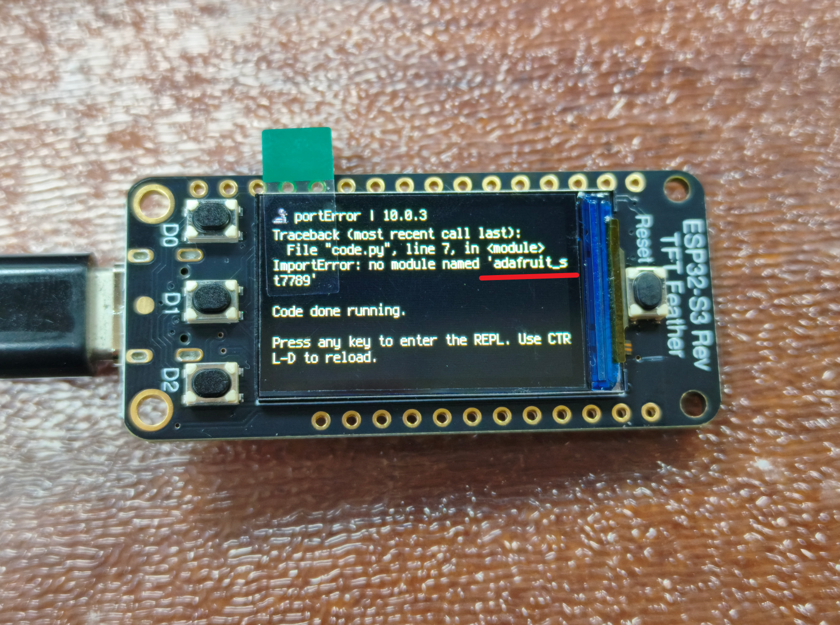
4. **预装情况阐述**:鉴于开发板频繁更新以及存储空间的限制,Adafruit出品的开发板并不会预装完整的库捆绑包。用户在使用时,需自行加载所需的库文件。同时,开发板对应指南中的示例代码,可能会依赖外部库。
5. **核心要点强调**:在探索CircuitPython的过程中,熟练掌握“如何将库加载到开发板”这一技能,是至关重要的核心需求。

彩虹呼吸灯
# SPDX-FileCopyrightText: 2021 Kattni Rembor for Adafruit Industries
# SPDX-License-Identifier: MIT
"""CircuitPython status NeoPixel rainbow example."""
import time
import board
from rainbowio import colorwheel
import neopixel

pixel = neopixel.NeoPixel(board.NEOPIXEL, 1)
pixel.brightness = 0.3


def rainbow(delay):
    for color_value in range(255):
        pixel[0] = colorwheel(color_value)
        time.sleep(delay)


while True:
    rainbow(0.02)
引脚说明


原理图

版块:
开发板测评
前天 18:57


全部评论